
93 Ramcharger -> 12V
 02-10-2012, 11:45 PM
#46
Registered User

Join Date: Apr 2007
Posts: 83
Likes: 0
Received 0 Likes
on
0 Posts
Very nice work... I have some rats nest of wiring I need to sort through, new coolant gauge to install, hook the tach up, think about considering the AC and then we'll be done... mostly.
 02-15-2012, 09:32 PM
#47
Registered User
Thread Starter
Core Support Modifications
Disclaimers:
1. I did this conversion a while ago so sorry if I leave anything out.
2. If I had time, a welder, and a press brake things would have gone differently. I had to get this truck on the road so I modified it, until it worked.
So here is our goal for reference:
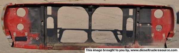
On each side of the radiator openings you can see:
1. Rectangular holes for the A/C Condenser
2. Long Oval holes for the Intercooler
3. Two small angle brackets located directly below the I/C openings to mount the I/C
4. On the far side of the opening (toward the outside of the truck) on either side we can also see a sheetmetal reinforcement bracket that runs from top to bottom of the core support. This serves two functions, one to provide an upper mount for the I/C and the second is to provide reinforcement (we'll see why later).
Here is where we are going to end up:
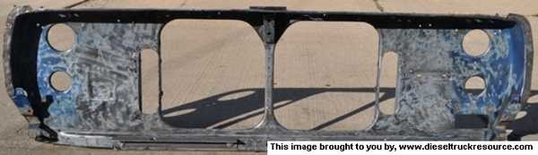
Sorry, I don't have a picture of the unmodified gasser version.
Here is a shot of the driver's side of the core support from there rear.

You have to trim out everything between the reinforcement brackets from the factory. You can also see how much of the flange I've had to remove to get the I/C to sit in place. Since I removed so much strength by doing this, I reinforced the area. I laid in a 1"x1" angle bracket to run the length of the support, it is held in place by JB weld and pop rivets. Between the mechanical attachment and the epoxy, I hoped to restore the strength I took away. It all fits... barely.
In addition, there is a hole just above the boss for the battery tray, that's a hole to mount the upper support for the I/C.
Next a picture of the back of the core support showing more sheet metal trimming.

All this needed to be removed in order to fit the big diesel radiator. It does fit... barely. Also visible is the added holes required to mount the top radiator brackets drilled into the flange. (Two holes located directly above the oval hole for the I/C opening).
Moving to the front of the core support.
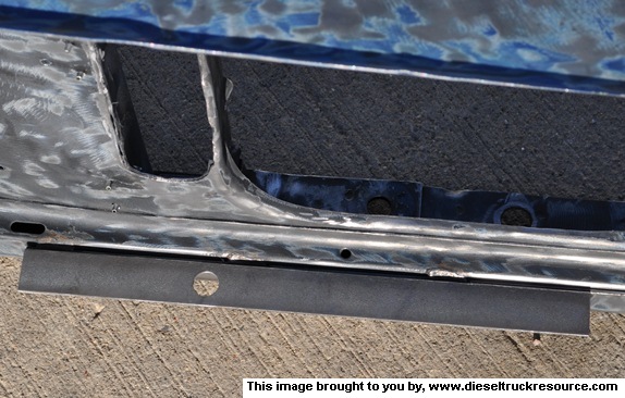
I needed to create a landing area for the I/C lower mounting locations. This is 2"x2" material drilled for the lower grommet. It is attached with two 3/8" bolts going through the core support, one at each end.
What should I have done better?
The lower radiator mount height is different between the diesel and gas. The diesel mounts the radiator about 3/4" higher, so the lower mounts hang in the air a bit when you mount the radiator.
1. I did this conversion a while ago so sorry if I leave anything out.
2. If I had time, a welder, and a press brake things would have gone differently. I had to get this truck on the road so I modified it, until it worked.
So here is our goal for reference:
On each side of the radiator openings you can see:
1. Rectangular holes for the A/C Condenser
2. Long Oval holes for the Intercooler
3. Two small angle brackets located directly below the I/C openings to mount the I/C
4. On the far side of the opening (toward the outside of the truck) on either side we can also see a sheetmetal reinforcement bracket that runs from top to bottom of the core support. This serves two functions, one to provide an upper mount for the I/C and the second is to provide reinforcement (we'll see why later).
Here is where we are going to end up:
Sorry, I don't have a picture of the unmodified gasser version.
Here is a shot of the driver's side of the core support from there rear.
You have to trim out everything between the reinforcement brackets from the factory. You can also see how much of the flange I've had to remove to get the I/C to sit in place. Since I removed so much strength by doing this, I reinforced the area. I laid in a 1"x1" angle bracket to run the length of the support, it is held in place by JB weld and pop rivets. Between the mechanical attachment and the epoxy, I hoped to restore the strength I took away. It all fits... barely.
In addition, there is a hole just above the boss for the battery tray, that's a hole to mount the upper support for the I/C.
Next a picture of the back of the core support showing more sheet metal trimming.
All this needed to be removed in order to fit the big diesel radiator. It does fit... barely. Also visible is the added holes required to mount the top radiator brackets drilled into the flange. (Two holes located directly above the oval hole for the I/C opening).
Moving to the front of the core support.
I needed to create a landing area for the I/C lower mounting locations. This is 2"x2" material drilled for the lower grommet. It is attached with two 3/8" bolts going through the core support, one at each end.
What should I have done better?
The lower radiator mount height is different between the diesel and gas. The diesel mounts the radiator about 3/4" higher, so the lower mounts hang in the air a bit when you mount the radiator.
02-15-2012, 09:36 PM
#48
Registered User
Thread Starter
Fuel Sending Unit
During the conversion I modified my fuel pickup ala BC847 in the "stickied" thread.
https://www.dieseltruckresource.com/...d.php?t=151190
Since my fuel lines were completely hosed on the gas version, I ran 3/8 line for the draw and return lines. Since BC used the spare bung, I took a chance and modified the fuel send and return bung in the same way. It worked and here is the result.
If you can find another spare bung, I would definitely go that route first. Using the send and return bung worked, but it wasn't as strong as the spare bung.
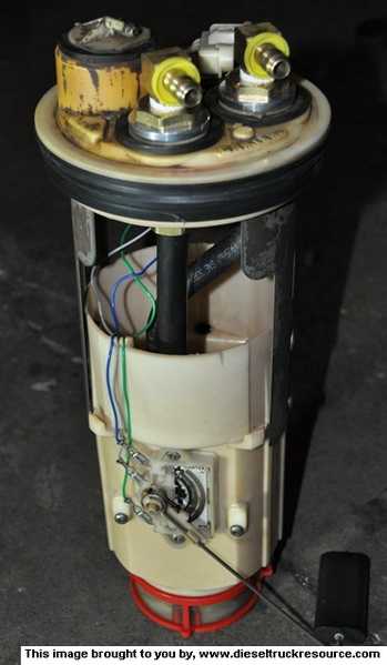
Thanks again David!
https://www.dieseltruckresource.com/...d.php?t=151190
Since my fuel lines were completely hosed on the gas version, I ran 3/8 line for the draw and return lines. Since BC used the spare bung, I took a chance and modified the fuel send and return bung in the same way. It worked and here is the result.
If you can find another spare bung, I would definitely go that route first. Using the send and return bung worked, but it wasn't as strong as the spare bung.
Thanks again David!
02-16-2012, 11:00 PM
#49
Registered User

Join Date: Oct 2006
Location: San Diego California
Posts: 198
Likes: 0
Received 0 Likes
on
0 Posts
Thanks Tower!!! That is just what I needed. I have a welder and a press and I think I see what you would have done with those tools. I will take pics along the way as well. My only hope is that it comes out somewhat near as clean as yours!!!
03-21-2012, 06:50 PM
#50
Registered User
Thread Starter
Grid Heaters - Manual wiring
***** I've seen a bunch of folks lately asking about manually wiring a grid heater so here's how I wired my Mutt. *****
I ran fused power from the 100A marine fuseblock when I ripped out the grid heaters (pics in post 41).
Power goes to a momentary switch in the dash. I used NAPA P/N ECH STB6301. The important thing is that the switch is normally in the OFF position, you push it ON, and it has a spring return to OFF when you let go of the button. NAPA has around 30 online I'm sure there are hundreds of them if you start looking.
From the switch in the dash it runs to the first grid heater, and then a bridge to the 2nd grid heater.
The ground circuit simply runs a bridge between the first and second grid heater and on to a battery ground. I ran mine back to the 100A marine fuseblock because I have it tied directly to battery ground.
The wiring to and from the dash goes through an existing grommet in the firewall for dash wiring. I just pushed the two wires I needed through the factory grommet.

The relays are WHITE-ROGERS 12V 100A, mfr P/N 120-105711 or Grainger item 6C017 (thanks Jim Lane! from an old post). Grainger description below:
"DC Power Solenoid, Coil Voltage DC 12, Amps 100, Coil Type Isolated, Contact Form SPNO, Coil Termination #10-32, Contact Termination 5/16-24, Contact Material Silver Alloy, Duty Cycle Continuous Mounting Base Std. Bracket, Series 120, Enclosure Dust And Water Resistant"
Disclaimer: I cheated on the wiring. From momentary switch it should have individual leads to the power side of the solenoids. Similarly, the solenoids should have individual grounds to the battery ground.
Does my method work? You bet! Is it perfect, nah, but I'm lazy and it works.
I ran fused power from the 100A marine fuseblock when I ripped out the grid heaters (pics in post 41).
Power goes to a momentary switch in the dash. I used NAPA P/N ECH STB6301. The important thing is that the switch is normally in the OFF position, you push it ON, and it has a spring return to OFF when you let go of the button. NAPA has around 30 online I'm sure there are hundreds of them if you start looking.
From the switch in the dash it runs to the first grid heater, and then a bridge to the 2nd grid heater.
The ground circuit simply runs a bridge between the first and second grid heater and on to a battery ground. I ran mine back to the 100A marine fuseblock because I have it tied directly to battery ground.
The wiring to and from the dash goes through an existing grommet in the firewall for dash wiring. I just pushed the two wires I needed through the factory grommet.
The relays are WHITE-ROGERS 12V 100A, mfr P/N 120-105711 or Grainger item 6C017 (thanks Jim Lane! from an old post). Grainger description below:
"DC Power Solenoid, Coil Voltage DC 12, Amps 100, Coil Type Isolated, Contact Form SPNO, Coil Termination #10-32, Contact Termination 5/16-24, Contact Material Silver Alloy, Duty Cycle Continuous Mounting Base Std. Bracket, Series 120, Enclosure Dust And Water Resistant"
Disclaimer: I cheated on the wiring. From momentary switch it should have individual leads to the power side of the solenoids. Similarly, the solenoids should have individual grounds to the battery ground.
Does my method work? You bet! Is it perfect, nah, but I'm lazy and it works.
03-22-2012, 11:36 PM
#51
Registered User
Join Date: Oct 2006
Location: San Diego California
Posts: 198
Likes: 0
Received 0 Likes
on
0 Posts

Thanks!!
03-23-2012, 12:40 AM
#52
Registered User
Join Date: Oct 2006
Location: San Diego California
Posts: 198
Likes: 0
Received 0 Likes
on
0 Posts
Thanks!! Great stuff!!!
 03-23-2012, 09:39 PM
#54
Registered User
Thread Starter
I have stock half ton springs in the rear with the overload leaf removed and the 3/4 ton 6" blocks in the back to make it level with the front. Basically, your measurement will be different. Please don't waste a couple hundred bucks off my measurement.
Front: I'll take a measurement tomorrow, but I remember thinking that the front driveshaft was shorter than the one I pulled from the RC. Remember, I came from an automatic truck with the NP241 to a manual G360 truck with the NP205. I can't remember if you are running a stick or auto in your conversion. I think you said it was a different chassis, so my measurement won't be helpful here. To finally answer your question, the driveshaft I pulled from the donor truck, bolted into my RC.
Thanks, much appreciated!
 03-25-2012, 11:02 PM
#55
Registered User
Join Date: Oct 2006
Location: San Diego California
Posts: 198
Likes: 0
Received 0 Likes
on
0 Posts
[QUOTE=DevilzTower;3090978]Rear: The 35 3/4 is the rear measurement. I WILL ADVISE that you go out an measure yourself once the drivetain is set in place.
I have stock half ton springs in the rear with the overload leaf removed and the 3/4 ton 6" blocks in the back to make it level with the front. Basically, your measurement will be different. Please don't waste a couple hundred bucks off my measurement.
Front: I'll take a measurement tomorrow, but I remember thinking that the front driveshaft was shorter than the one I pulled from the RC. Remember, I came from an automatic truck with the NP241 to a manual G360 truck with the NP205. I can't remember if you are running a stick or auto in your conversion. I think you said it was a different chassis, so my measurement won't be helpful here. To finally answer your question, the driveshaft I pulled from the donor truck, bolted into my RC.
I am running a Loadflite 727 with NP203 (or so I thought) but ran into a snag today. The bolt pattern on the 203 doesnt match my diesel 727. I was thinking of just swapping out the output shaft housings but they are 3 inches different in length. So my next question is for anyone with tranny experience. Can I just swap the output shafts as well as the housings? I HOPE SO!!! More to follow I am sure.
Thanks for the help!!
I have stock half ton springs in the rear with the overload leaf removed and the 3/4 ton 6" blocks in the back to make it level with the front. Basically, your measurement will be different. Please don't waste a couple hundred bucks off my measurement.
Front: I'll take a measurement tomorrow, but I remember thinking that the front driveshaft was shorter than the one I pulled from the RC. Remember, I came from an automatic truck with the NP241 to a manual G360 truck with the NP205. I can't remember if you are running a stick or auto in your conversion. I think you said it was a different chassis, so my measurement won't be helpful here. To finally answer your question, the driveshaft I pulled from the donor truck, bolted into my RC.
I am running a Loadflite 727 with NP203 (or so I thought) but ran into a snag today. The bolt pattern on the 203 doesnt match my diesel 727. I was thinking of just swapping out the output shaft housings but they are 3 inches different in length
. So my next question is for anyone with tranny experience. Can I just swap the output shafts as well as the housings? I HOPE SO!!! More to follow I am sure.Thanks for the help!!
04-11-2012, 12:52 PM
#56
Registered User
Join Date: Dec 2010
Location: South Lake Tahoe, CA
Posts: 69
Likes: 0
Received 0 Likes
on
0 Posts
Devilz tower, That is a beautiful RC. I sure like the 91.5-93 grille. I wish I had stuck with the manual in mine, but alas my insurance rates are too high already.
The front DS is indeed longer on the AT vs MT, My RC was originally 360/A518/NP241 and the front driveshaft was almost the same length as the one currently on my RC with a 6BT/A518/NP205
On my auto trans RC the front is actually longer than my rear. My rear is something like 31"
SDmark, I'd be leery using a gas output shaft behind a diesel...

Thread
Thread Starter
Forum
Replies
Last Post
cLAYH
1st Gen. Ram - All Topics
1
01-16-2005 10:46 AM