When you click on links to various merchants on this site and make a purchase, this can result in this site earning a commission. Affiliate programs and affiliations include, but are not limited to, the eBay Partner Network.
1st Gen. Ram - All TopicsDiscussion for all Dodge Rams prior to 1994. This includes engine, drivetrain and non-drivetrain discussions. Anything prior to 1994 should go in here.
Could you post up Sheet AD 22, I noticed that on the 91 wiring diagram (Sheet 21) the headlamp switch's switched ground also has a circuit that goes to the snow plow provision on sheet 22. On the 93 wiring diagram that circuit is shown as going to the tachometer provision.
I would think that if the DRL module output is wired to the headlights after the relays, and the parking light circuit is still going to the DRL, it should work normally.
In theory, if the headlight switch is off, the DRL module uses a few inputs to supply the headlamps with a lower voltage to dimly light them. As soon as the headlamp switch if moved from off, ie parking lamp circuit is energized, the DRL shuts off and lets the normal circuitry run the lights.
It should work if you move the wires that run from the DRL module to the left headlamp connector to the same location on the connector now on the headlamp that's powered from the relay mod.
In my 93 diagrams I notice that the DRL module is wired to both high and low beam circuits at the right headlamp connector. The SM doesn't have squat for theory, other than the DRL module lights the headlamps at less than 50% brightness. I'm guessing it lights both filaments at about 6V.
I'd bet it wouldn't light LED's at all. In that case you could wire the DRL module to bumper or grill mounted running lights.
I spliced into the steering column wiring instead of discounting it as you suggest and it everything worked. However, the low beam trigger wire needed to be disconnected, as it caused the relay to chatter.
How to get Canadian DRL working with a relay harness.
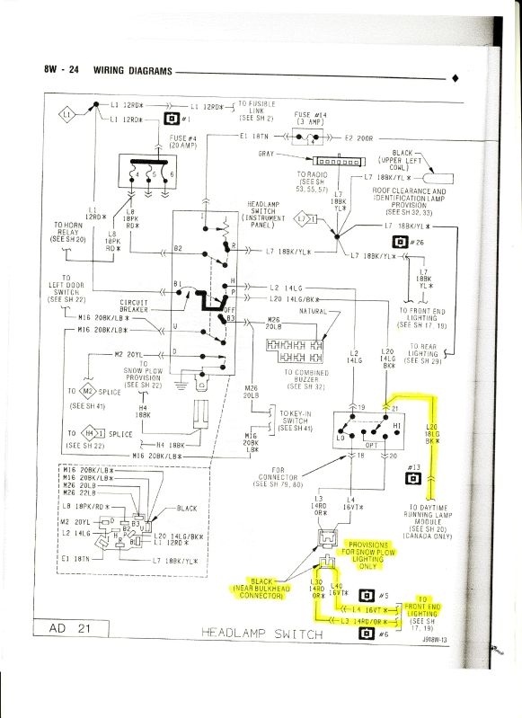
Thanks for posting the wiring diagram, I marked it up here for clarity. This is how I got mine working on my truck. You don't need to go digging in the truck cab for wires with this setup. All the signal you need is at headlight harness.
A relay setup will not work until you separate the DRL wires from the passenger harness, the pulse width modulated drl voltage will buzz the heck out of the relays. Since it is all taped up, the easiest way is to cut both reds and both purple wires (the pairs going to the high beam and low beam on the connector) and test. With the truck not running (so as not to activate the DRL module if you just moved it), with the low beams on, mark which purple wire has 12v. With the high beams on mark which red wire has 12v. The other two wires are by elimination the DRL wires.
Now proceed to build your relay harness like normal. When done, wire the DRL wires to the headlamp side of your relay harness. So just like the stock setup, one of your headlights will have 5 wires going to the harness. A ground, a high and low beam from your relay power, and a high and low beam from the DRL module.
Now when the lights are on they go through your relays. When off, the DRL module powers the lights as it always did with PWM voltage to get dim driving lights.
Last edited by mpatl; 11-24-2015 at 11:39 AM.
Reason: clarity
Thanks for posting the wiring diagram, I marked it up here for clarity. This is how I got mine working on my truck. You don't need to go digging in the truck cab for wires with this setup. All the signal you need is at headlight harness.
A relay setup will not work until you separate the DRL wires from the passenger harness, the pulse width modulated drl voltage will buzz the heck out of the relays. Since it is all taped up, the easiest way is to cut both reds and both purple wires (the pairs going to the high beam and low beam on the connector) and test. With the truck not running (so as not to activate the DRL module if you just moved it), with the low beams on, mark which purple wire has 12v. With the high beams on mark which red wire has 12v. The other two wires are by elimination the DRL wires.
Now proceed to build your relay harness like normal. When done, wire the DRL wires to the headlamp side of your relay harness. So just like the stock setup, one of your headlights will have 5 wires going to the harness. A ground, a high and low beam from your relay power, and a high and low beam from the DRL module.
Now when the lights are on they go through your relays. When off, the DRL module powers the lights as it always did with PWM voltage to get dim driving lights.
Sweetness! Thank you for taking the time to update this thread....always appreciated!
I need a Canadian Volunteer to try this circuit on their headlights.
It is very simple consisting of only 2 relays and I think it should work, I would have developed one a long time ago but since I have nothing to test it on I can only see it in my mind.
Here in the factory diagram you can see how the lamps are connected left and right in a conventional manner, the DRL module is connected to the harness through the Right side headlamp (I traced out the circuit in yellow highliter so it is easer to see) you can see that the DRL is connected to both Low and High Beam filaments, but I am not exactly sure why.
As far as I understand DRL's and there are different systems, the High Beam filament is being driven at a decreased output usually 70% by a PWM (pulse width modulation) signal from the DRL module.
This would account for the relay chattering when it was connected across the PWM's output.
This is the right side of the truck, at the top right you can see the DRL module and its connections.
How it works:
Both Low and High Beam relays are configured backwards compared to the relays on Federal (USA) sold trucks.
The headlamp filaments are connected to Term #30 Common, Term#87a N.C. is connected the the existing DRL circuit while Term #87 N.O. is connected to the battery and supplies full voltage and current.
You can see in my circuit the headlamps will remain in the factory DRL circuit and function properly as long as the headlamps are turned off but as soon as the low beams are activated the low beam relay will trigger and toggle the headlamps from DRL over to full power.
Use a Bosch, Tyco or other good quality 5-terminal ISO relay for this upgrade.
Term #30 = Headlamps
Term #85 = Coil ground
Term #86 = Coil + signal LOW BEAM L-4 16-Violet wire HIGH BEAM L-3 14-Red wire
Term #87a = factory DRL circuit from RIGHT side headlamp socket
Term# 87 = (+) 12-volts and circuit breaker
The relay trigger wires from each Term #86 of each relay will be connected to the Black 2-blade connector inside the cab above the base of the steering column up near the bulkhead connector, if my idea is correct you will not reconnect the opposite end.
Use a 12-volt test light to determine which side of the connector to connect your wires to.
I need some of you to give this a try and let me know if there are any issues that I need to change in the design.
Once I know it works I can show how to wire up the harness.
Don't forget to use good sockets and make a good ground connection from the headlamps to body.
Also make sure the DRL power it taken from the RIGHT side headlamp socket or it will not work.
02/25/2013
Jim
Hi everyone, it�s been a while since anybody has touched this thread.
Jim, have you ever looked at wiring relays straight into the existing harness? I�ve been working on a fusable link delete for my 92 Club Cab, and the Power Distribution Box that I�m wiring in has room for both a low beam and high beam relay. I�ve drawn a rough wiring diagram, wondering if someone could check my work. Going to splice into the low beam and high beam wires a couple inches below the bulkhead connector for my #86 trigger wires, and splice BOTH the #87a N.C. and #30+ into the existing harness off those cut connections. My 87 N.O. will be wired to a 30amp Maxi fuse internal to the PDB, and 85 to a ground next to the box.
Will be testing when I swap my new engine harness into the truck.
Anybody see anything wrong with this before I test it out?

 01-27-2015, 02:06 AM