Fusable Links STINK !
 05-09-2014, 06:46 PM
#46
Registered User
Thread Starter
Join Date: Dec 2010
Location: Land of the Toxic Avenger
Posts: 6,776
Received 1,640 Likes
on
1,115 Posts
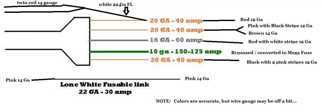
Don't know if this will help anyone else, but this is how my truck was wired...


 05-11-2014, 01:24 PM
#48
Registered User
Join Date: May 2005
Location: Edmonton,Alberta
Posts: 805
Likes: 0
Received 0 Likes
on
0 Posts
Fusable Links STINK !
I plan on doing this swap/upgrade. The previous owner of my 92' had a few FL pop on him and decided a cycling circuit breaker was an okay fix...
11-09-2014, 09:17 PM
#49
Registered User

This is probably a simple question but I'm electronically challenged. I was replacing a battery terminal and the fusible link on the big wire that connects to the positive side of the battery broke. It had been tampered with by the PO. I'm thinking about just installing a resettable circuit breaker in place of the FL. If i do, what amperage rating do I need. If not, can you buy fusible link wire that size at an auto parts store. I don't wanna to change the current wiring out like some have, I just want a good dependable fix
11-10-2014, 11:21 AM
#50
Registered User
This is probably a simple question but I'm electronically challenged. I was replacing a battery terminal and the fusible link on the big wire that connects to the positive side of the battery broke. It had been tampered with by the PO. I'm thinking about just installing a resettable circuit breaker in place of the FL. If i do, what amperage rating do I need. If not, can you buy fusible link wire that size at an auto parts store. I don't wanna to change the current wiring out like some have, I just want a good dependable fix
These circuits all carry significant current, so be sure your connections are up to it. I use a crimp sleeve, solder, and heat shrink.
Another usable factoid is that the rule of thumb for wire current carrying size is "two in hand minus 3". In other words, the double 14G wire above would have the same capacity as an 11G wire. It feeds a 12G circuit, so it is big enough plus a little.
You can use circuit breakers, but I wouldn't use auto reset breakers. If something goes wrong and blows a fusible link, it is usually way above the carrying capacity of most of the protected circuits, thus stressing the failing one drastically. An auto reset breaker could easily equal a wiring harness fire.
11-10-2014, 10:55 PM
#51
Registered User
Thanks for the info. I couldn't find the right size link wire so I got 2 copper terminal ends and crimped/soldered on each side of the broken link and just installed a resettable 150 amp circuit breaker (not an auto reset). This was on the main power cable after it leaves the battery so I had no power anywhere when the link failed
11-11-2014, 06:19 AM
#52
Registered User
Thread Starter
Join Date: Dec 2010
Location: Land of the Toxic Avenger
Posts: 6,776
Received 1,640 Likes
on
1,115 Posts
Considering my truck was wired as from the factory with that double red 14 spliced into the 22ga FL, not sure I follow your logic. There was NO EVIDENCE that this was tampered with by any previous owner or mechanic. The factory coverings were on the harness when I took it apart. The truck was 20+ years old when I bought it, so it's possible, but I saw no indication that the "splice" wasn't anything other than a factory process.
I can say that my truck has been driven around since I did this replacement in April,and nothing has failed, no fuses have popped, and no truck fires were started by what I've done here....
Come to think of it..... I used your previously posted diagram to wire my truck, so if anything was substituted, I guess it's based upon your original post, eh ?
Don't know if you realize this or not, but you have an amazing way of making it seem as though you're putting the work down of others, while pretending, or maybe not actually being aware that you're doing so. Even more confusing is the fact that I used your information, and your diagram to help me do this. If you felt something was substituted incorrectly, or something was done wrong, maybe it would have been more appropriate if you mentioned it back in April. NO ?
11-11-2014, 08:53 AM
#53
Registered User
Really ?
Considering my truck was wired as from the factory with that double red 14 spliced into the 22ga FL, not sure I follow your logic. There was NO EVIDENCE that this was tampered with by any previous owner or mechanic. The factory coverings were on the harness when I took it apart. The truck was 20+ years old when I bought it, so it's possible, but I saw no indication that the "splice" wasn't anything other than a factory process.
I can say that my truck has been driven around since I did this replacement in April,and nothing has failed, no fuses have popped, and no truck fires were started by what I've done here....
Come to think of it..... I used your previously posted diagram to wire my truck, so if anything was substituted, I guess it's based upon your original post, eh ?
Don't know if you realize this or not, but you have an amazing way of making it seem as though you're putting the work down of others, while pretending, or maybe not actually being aware that you're doing so. Even more confusing is the fact that I used your information, and your diagram to help me do this. If you felt something was substituted incorrectly, or something was done wrong, maybe it would have been more appropriate if you mentioned it back in April. NO ?
The 12G red wire, which feeds the ignition switch, is originally wired to one of the orange fusible links from the duck foot.
It is possible to make a professional splice in the field.
I assumed the 14g red wires in your diagram went to the battery, judging from the orientation of them on the diagram. That may have been a false assumption. If you could tell me where they go, I might be able to figure it out.
My working diagrams are from the 1993 Dodge FSM. Should be exactly the same as yours.
11-11-2014, 04:43 PM
#54
Registered User

On my 91.5 the two 14g red wires were hooked up in the same way as the diagram. One of them came from the battery and the other one went back to the computer so the one red wire fed power to both the computer and the fusable link. My harness had never been cut up until I removed the fusable links.
11-11-2014, 05:48 PM
#55
Registered User
Thread Starter
Join Date: Dec 2010
Location: Land of the Toxic Avenger
Posts: 6,776
Received 1,640 Likes
on
1,115 Posts
, please provide a link to the offensive post in April.
It is possible to make a professional splice in the field.
I assumed the 14g red wires in your diagram went to the battery, judging from the orientation of them on the diagram. That may have been a false assumption. If you could tell me where they go, I might be able to figure it out.
My working diagrams are from the 1993 Dodge FSM. Should be exactly the same as yours.
I agree wholeheartedly that it is indeed possible to make a professional splice, but these (to me) looked 100% factory. Right now, I cannot tell you where the red 14(s) goes, but I believe you are right that they went to the battery, and somewhere else. Can't remember yesterday, never mind April. I gladly will mail you a disc copy of the FSM from 1992 if you wish. Just PM me an address or P.O. box to send it to, and it's yours, no questions asked, and no keeping your address for future use in a terrorist attack...

Not that it matters Mr. J. I think you are a very intelligent, and valuable source of this site. It's just sometimes words written by all of us (myself included) seem to come out a bit crass sometimes, and it's a good thing (to me, anyways) that we're reminded of the fact that we're all in this mess together... as brothers of sorts.
11-11-2014, 06:10 PM
#56
Administrator
Not that it matters Mr. J. I think you are a very intelligent, and valuable source of this site. It's just sometimes words written by all of us (myself included) seem to come out a bit crass sometimes, and it's a good thing (to me, anyways) that we're reminded of the fact that we're all in this mess together... as brothers of sorts.
11-11-2014, 08:09 PM
#57
Registered User
I agree wholeheartedly. I think that sometimes predictions are stated as fact, i.e. what "will" happen, rather than an opinion as to what "may" happen. If what had been said to me about what "will" happen was true, I would have burned to death from auto-ignition of my anti-freeze...Mark

Actually I agree also, we're all in the same boat...er truck.
OK, now I've tracked it down on page 6 of the wiring diagrams. The two red wires are both PCM power feed. One goes to the ASD, and the other goes directly to the PCM. By convention, diagrams usually flow from left to right, top to bottom. The red wires should have gone off the right side of the diagram for readability. Technically the diagram is correct. I was in error to assume that it diagrammed a repair.
The orange link feeds the ignition switch and the white link.
The white link goes on to feed the PCM through the red wires as I noted above.
11-11-2014, 08:27 PM
#58
Administrator
12-10-2015, 12:21 PM
#59
Registered User

This is a great thread, but no consensus was reached regarding the amp rating for the 10 gauge fusible link. My 1993 manual specifies that fusible link at 120 amps, as NJTman pointed out in the thread. But, j_martin suggests 150-175 amps. I'm about to do this modification and hope someone can pin this down. Thanks
12-10-2015, 01:09 PM
#60
Registered User
This is a great thread, but no consensus was reached regarding the amp rating for the 10 gauge fusible link. My 1993 manual specifies that fusible link at 120 amps, as NJTman pointed out in the thread. But, j_martin suggests 150-175 amps. I'm about to do this modification and hope someone can pin this down. Thanks