
Crewcab update...
 01-25-2014, 03:19 PM
#496
Registered User
Thread Starter

Well I'm working on getting the fuel tank and lines in today. Then it's drive shafts, and interior and wiring.
Hope within the next month I should be rolling.
 01-27-2014, 06:38 AM
#497
Registered User

I really like the way that strapping turned out. Doesn't look bad at all. Gross on the cab access holes, mine were not that bad on the outside. Just the driver side had a dead rabbit inside of it. Don't ask how it got there, cause I couldn't figure it out.
02-04-2014, 09:01 PM
#498
Registered User
Join Date: Sep 2010
Location: Sedgewick, AB
Posts: 1,059
Likes: 0
Received 0 Likes
on
0 Posts
Wow used to follow this thread all the time been busy and almost forgot I had this account but it amazes me the talent and attention to perfection you have for the truck when its done it'll be far better than new best of luck in the finishing touches!
02-07-2014, 12:27 AM
#500
Registered User
Thread Starter
Ok I'll try again tonight....Have I mentioned how much I hate photobucket!! 
I have been working on the crewcab...just been too busy to update regularly.
So here's what I've gotten done in the last week or so. I got the fuel tank and lines in and hooked up.
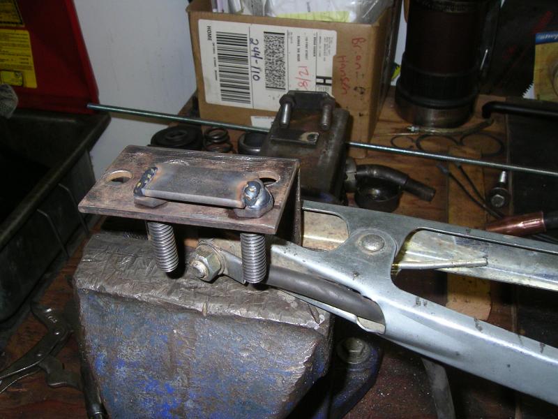
I did do one little modification when installing the fuel tank straps. Since the 84 chassis uses a little different tank strap then the later ones. The 84 straps are bolted to the bottom of the frame rail with two bolts and nuts, behind the fuel tank. The problem with this set-up is that you can not remove those nuts since the bolts will spin once loosened.
So my solution was to weld a small piece of flat bar between the bolts. Thus making a simple U-bolt that can be unbolted anytime.
I have been working on the crewcab...just been too busy to update regularly.
So here's what I've gotten done in the last week or so. I got the fuel tank and lines in and hooked up.
I did do one little modification when installing the fuel tank straps. Since the 84 chassis uses a little different tank strap then the later ones. The 84 straps are bolted to the bottom of the frame rail with two bolts and nuts, behind the fuel tank. The problem with this set-up is that you can not remove those nuts since the bolts will spin once loosened.
So my solution was to weld a small piece of flat bar between the bolts. Thus making a simple U-bolt that can be unbolted anytime.
 02-07-2014, 12:36 AM
#501
Registered User
Thread Starter
The nylon fuel lines were pre-bent for the clubcab chassis....but I made them work. Used a number of old heater hose zip tied to them to make sure they would not rub on anything.
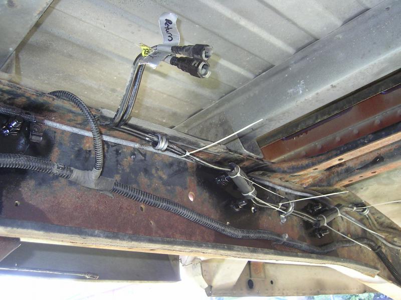
Had to lengthen them 11". Staggered my cuts and used 5/16" brake line make the splice.

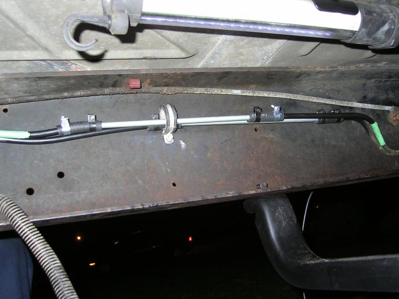

Had to lengthen them 11". Staggered my cuts and used 5/16" brake line make the splice.

 02-07-2014, 12:42 AM
#502
Registered User
Thread Starter
Removed all the dash cluster and wiring. Also managed to wrestle out the 7 5/16" bolts from under the window seal. Got the firewall all stripped out on the drivers side.
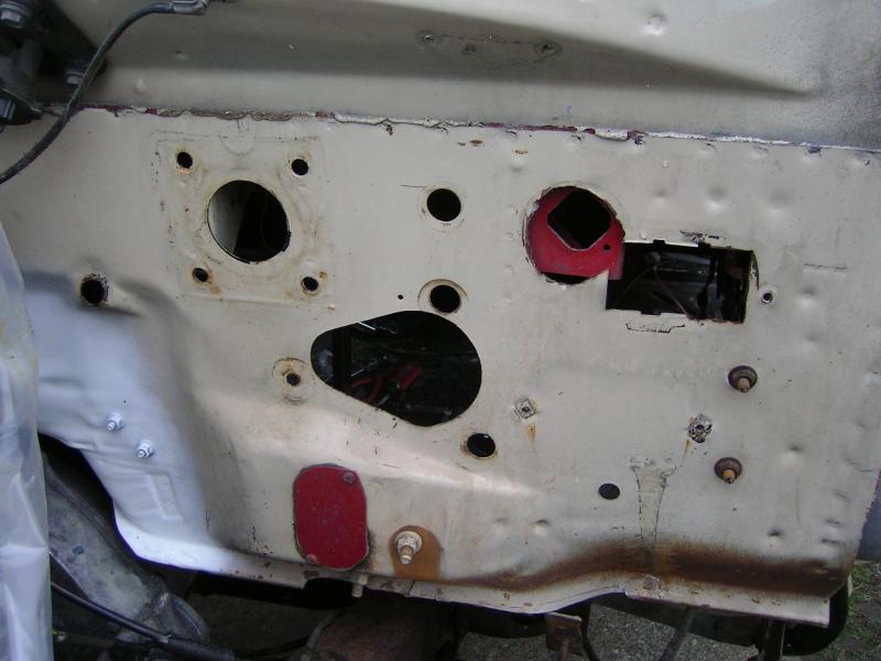
Man I hate people who do hack work!! Just makes more work for me to re-do it properly.
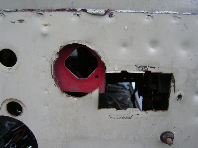
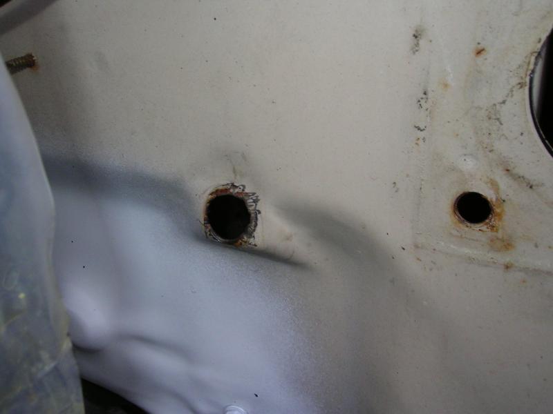
Going to finish stripping the dash out, then I can weld in new material and re-shape the holes, and add the ones necessary for the 93 wiring and such.

Man I hate people who do hack work!!
Just makes more work for me to re-do it properly.

Going to finish stripping the dash out, then I can weld in new material and re-shape the holes, and add the ones necessary for the 93 wiring and such.
02-07-2014, 12:53 AM
#503
Registered User
Thread Starter
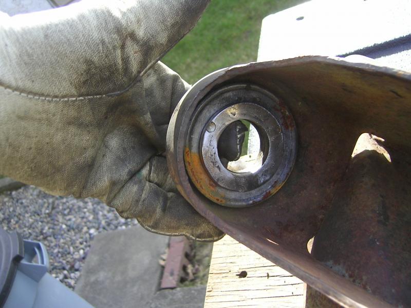
Also got my driveshafts all done. I ordered all new Spicer U-joints, Cardan joint rebuild kit, and carrier bearing.
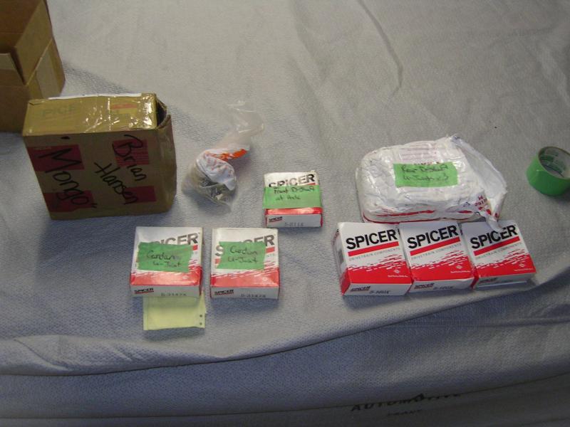
Dismantled everything and cleaned it all up the best I could.
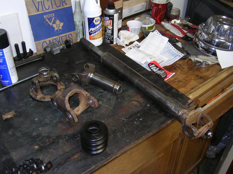
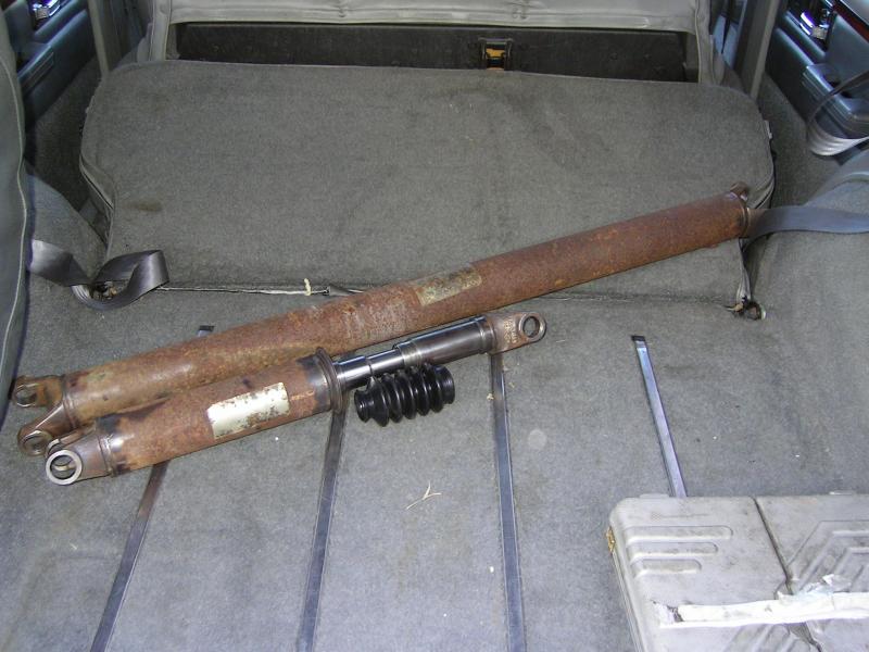
I called my local driveline shop and asked them how they wanted me to measure things. Turned out I needed 29.75" length for the front drive shaft.
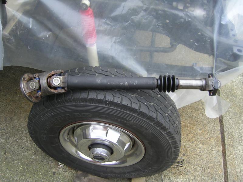
Then the 2 piece rear I needed 19" for the shaft from transfer case to center line of the carrier bearing. Then 75" from carrier bearing center line to rear axle. They ended up having to replace both ends on the long driveshaft. The bores for the cups were worn out.
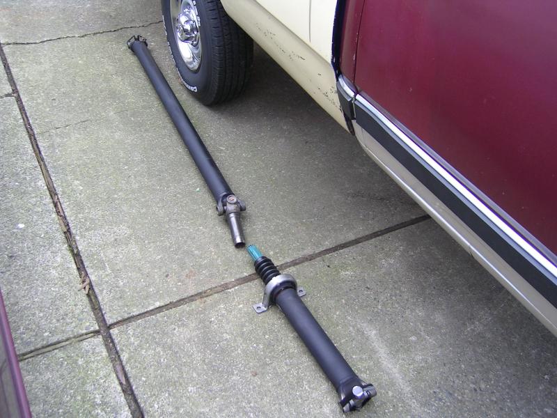
They did a very nice job on everything. Not cheap getting 3 drive shafts done. Shorten front one...then lengthen both rears, with 2 new ends. But they did install all the U-joints and and hardware for free. But at least everything is New and ready for another 260K Km's....
02-07-2014, 01:01 AM
#504
Registered User
Thread Starter
4wd front axle bumpers
Little problem I had. I have been trying to find the Moog K7282 axle bumpers for a long time now. Tried all the local jobbers...Canada and USA. I eventually thought I had found some through Jegs. Their website said they had a bunch in stock....so I went ahead and ordered them. I received notice that they were back ordered. This went on for almost 2 months before I cancelled the order.
I then was poking around my local Lordco and noticed some axle bumpers in the "Help" section. They sure looked like the ones I needed. I had the parts guy run the number...they were for 80-93 ramcharger....yup should work!!

So if you are looking for these...just look/order these ones and you should be good to go!!
02-07-2014, 01:14 AM
#505
Registered User
Thread Starter
Pulled apart the front of the motor to check the KDP and case bolts. Case bolts were still nice and tight. I tabbed the KDP with an old U-joint axle strap...someone mentioned doing this so I thought I'd try it.
Little work with the rat file to open up the hole. Then cut and grind until it fit perfect.
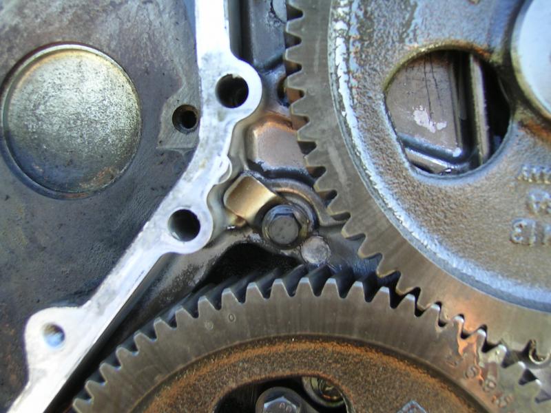
And a little trick I use to make sure I get the front timing case cover bolts back in the right location. Since there are short, and long bolts.
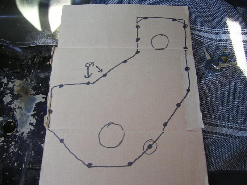
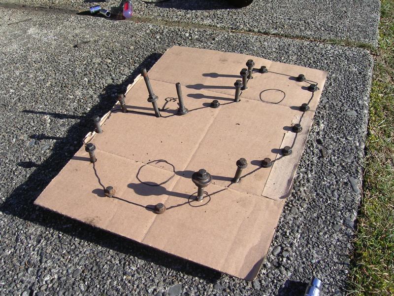
Little work with the rat file to open up the hole. Then cut and grind until it fit perfect.

And a little trick I use to make sure I get the front timing case cover bolts back in the right location. Since there are short, and long bolts.

 02-07-2014, 01:25 AM
#506
Registered User
Thread Starter
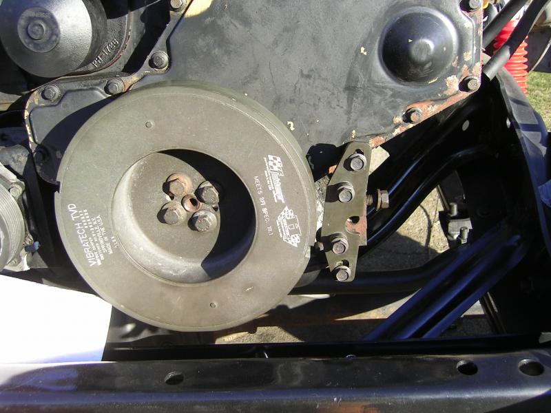
Then it was on to the installation of the fluidampr. Since this is a 93 motor I had to use the CPS relocation bracket. I looked on-line and could not find any pics of how this all went together...and the instructions that came with the kit were vague at best!
So I'll post up on what to do.
Once the timing case cover crank seal has been replaced, and the cover is back in place, you can install the fluidampr with the 4 - 15mm crank bolts. Then remove the two bolts on the lower LH side of the motor. The instructions that came with the CPS relocation kit were not very clear here. These are the ones you need to remove.
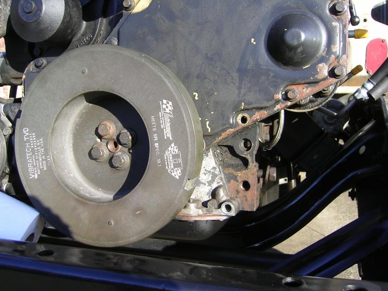
Then install the new spacer/bolts. These are 19mm.
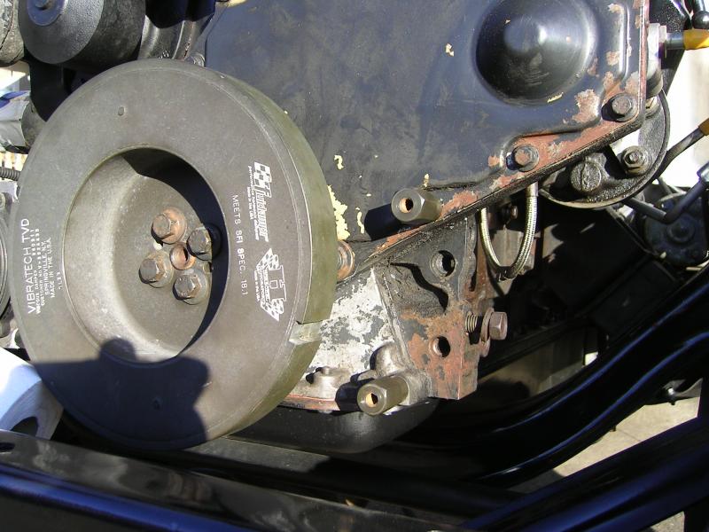
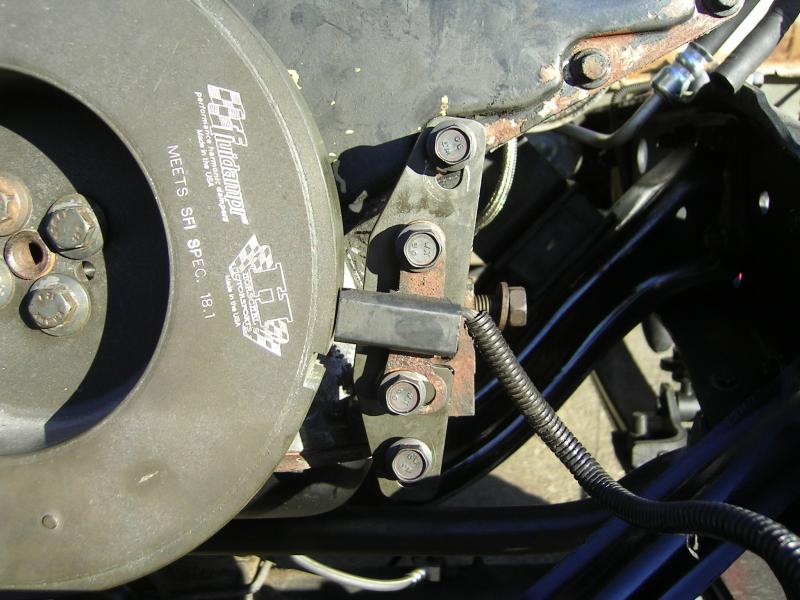
And now the main bracket.
So I'll post up on what to do.
Once the timing case cover crank seal has been replaced, and the cover is back in place, you can install the fluidampr with the 4 - 15mm crank bolts. Then remove the two bolts on the lower LH side of the motor. The instructions that came with the CPS relocation kit were not very clear here. These are the ones you need to remove.

Then install the new spacer/bolts. These are 19mm.

And now the main bracket.
 02-07-2014, 01:35 AM
#507
Registered User
Thread Starter
Now it should have been easy and just re-install the Crank Postion Sensor (CPS) and adjust the gap... 0.049 to 0.051, and your done. Nope not for me!
Turned out the CPS I have on my motor is a little different. I tried every way possible to get things to line up. I was just not able to get any clearance between the CPS and the fluidampr.
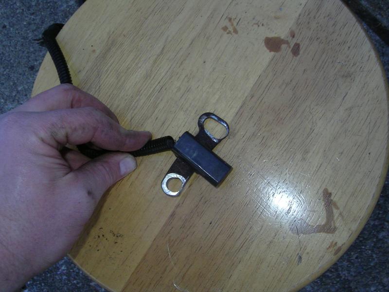
Turned out that after searching pics on-line I think the mounting bracket changed at some point.
Here's my CPS and bracket....after my modification with the rat file.
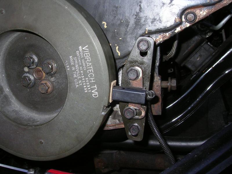
And I was finally able to get my .050" air gap.
 02-07-2014, 01:43 AM
#508
Registered User
Thread Starter
Oh and one more thing with the fluidampr install. Make sure you put your belt over the crank pulley before installing the CPS relocation kit.
Also While I had the front of the motor apart I decided to pop out the water pump for an inspection. Glad I did because I could see that there had been coolant weeping out of the water pump. So I tossed in a new one I had in the garage.
Also While I had the front of the motor apart I decided to pop out the water pump for an inspection. Glad I did because I could see that there had been coolant weeping out of the water pump. So I tossed in a new one I had in the garage.
02-07-2014, 02:06 AM
#509
Registered User
Thread Starter
If your installing a fluidampr on a non-IC motor (89, 90, early 91) then you should be OK with fan blade clearance, but double check first. On the 91.5 to 93 motors you are more then likely going to have clearance issues between the fan and fluidampr.
I had a new fan from a 2nd Gen on my 89 motor, with a new clutch assembly. I decided to compare it to the original assembly I pulled off the 93 motor. Turned out the fans are the same, but the clutches are a bit different.
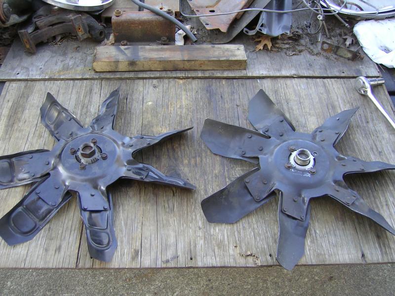
but the distance between the end of the clutch bolt, and the body of the fan was different. The OEM 93 unit was a tad longer then the 2nd Gen fan and new clutch. The difference was about 0.20" longer for the 93 clutch.
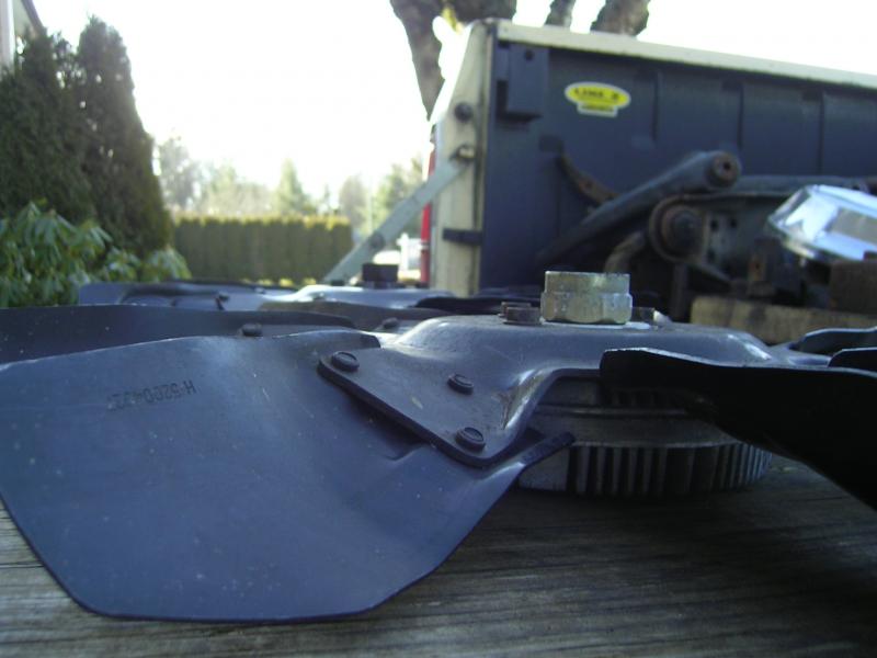
So I swapped the fans around and used the OEM 93 clutch.
02-07-2014, 02:15 AM
#510
Registered User
Thread Starter
So I first modified a washer that was about 0.125" thick. Wish I had a milling machine...I had to resort to rat files, and drum sand discs, and round flapper discs.
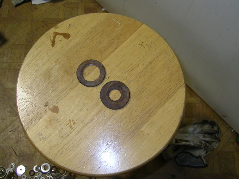
Once installed the fan was just kissing the fluidampr. So I needed a thicker washer. I found one spot welded to the old 2wd front cross member from the crewcab. Had to drill out 3 spot welds.
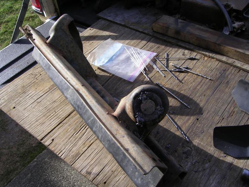
Then used a 60 grit flapper disc on my 4.5" grinder to slowly turn down the outside diameter....You can see it was a fair amount!!
This washer was about 0.20"...and was perfect!!

Once installed the fan was just kissing the fluidampr. So I needed a thicker washer. I found one spot welded to the old 2wd front cross member from the crewcab. Had to drill out 3 spot welds.

Then used a 60 grit flapper disc on my 4.5" grinder to slowly turn down the outside diameter....You can see it was a fair amount!!

This washer was about 0.20"...and was perfect!!