
Chas'in Leaks . . .
 02-28-2008, 03:42 AM
#16
Administrator

I have seen these at our local Napa but I am not sure how they would work for the engine but they would at least might save the radiator.
If Jegs sells them then I think they should have done some research on them as far as not being a scam
http://www.jegs.com/p/Ve-Labs/874787/10002/-1
When I worked on Cummins engines in transit coaches they all had what was called a Perry Filter. It was a small tank that was plumbed into the cooling system as a bypass and inside of it was a sock that contained Zinc Chromate and below the sock was a Zinc anode, the coolant was pee yellow. In all of the years I have worked on then I do not ever remember seeing corrosion as being an issue in them, the engines had millions of miles on them. I�ll admit these were wet sleeve engines.
Some of the old timer mechanics would muck up the works when their ideas was to add machinist milk to the mix. and I think that lowers the effency of the coolant.
Quote:
Further, keeping tabs on the antifreeze is a good idea. In addition to the freeze thing, there's a bunch of additives that control foaming, keep dirt in solution, lubricate, and those associated with controlling corrosion itself. They include chemicals that form protective films on the components further isolating them from free oxygen as well as that dissolved. It goes on.
True true but you also want to keep the antifreeze changed before it gets acidic and turns on the engine it was protecting. And lot of the destruction can come from electrolysis. Anyone who has had to repair a cheap copper repipe job will have seen this.
Your engine is looking nice, How are the A/C lines where they get close to the turbo from the heat?
Man I could not imagine having to work on anything when it is that cold, a freezing winter for me is 60*
I'm not sure about the anode thing Jim.
I do know that one of the best thing's you can do for most any water cooled engine as such is to be sure you run the correct radiator cap as well as a working overflow tank.
We need to be sure the radiator cap is the type that not only burps any trapped air on heating the fluid (expansion), but also allows siphoning fluid back into the system upon cooling (contraction). The goal being that ALL gases are disassociated and expelled from the system. No oxygen in the circuit, no common corrosion.
Further, keeping tabs on the antifreeze is a good idea. In addition to the freeze thing, there's a bunch of additives that control foaming, keep dirt in solution, lubricate, and those associated with controlling corrosion itself. They include chemicals that form protective films on the components further isolating them from free oxygen as well as that dissolved. It goes on.
RuralCruiser007, I'm gonna wimp-out and use the boom on the tractor. I can set the draft control such that if it begins to lift the front wheels, it'll back off automatically.

I've been slow in getting to it what with work, and windy-cold.
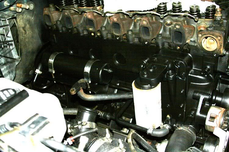
I have completed the task of removing and stripping both paint and any rust from all the hard-pipe associated with the cab heater and transmission heat exchanger. I had to remove the turbo down-pipe to allow the one coolant pipe to get around the trans exchanger's mounting bracket. I then had to remove the heat exchanger itself to get that pipe out from behind the same bracket.
I chemically stripped the pipes then scrubbed them with a stainless scouring pad. Got the rust off what little there was and struck them with two coats of paint. The heat exchanger has a very thick coating of paint. It is in good shape though there was a little corrosion of the tank adjacent to the water nipples. I got those spots down to clean metal and repainted as well.
It was a pain for sure what with using the installed valve springs as a place to kneel while you're dinking around with the exchanger fittings for example. Still though, that and replacing those little 90* x 5/8" rubber hoses should go well toward keeping the green in. The new engine oil cooler will help ensure the green and black don't go to making a funky soup.
Pardon the weird picture. With everything painted satin black, I had to alter it quite a bit so one can see at least some of the stuff.
I do know that one of the best thing's you can do for most any water cooled engine as such is to be sure you run the correct radiator cap as well as a working overflow tank.
We need to be sure the radiator cap is the type that not only burps any trapped air on heating the fluid (expansion), but also allows siphoning fluid back into the system upon cooling (contraction). The goal being that ALL gases are disassociated and expelled from the system. No oxygen in the circuit, no common corrosion.
Further, keeping tabs on the antifreeze is a good idea. In addition to the freeze thing, there's a bunch of additives that control foaming, keep dirt in solution, lubricate, and those associated with controlling corrosion itself. They include chemicals that form protective films on the components further isolating them from free oxygen as well as that dissolved. It goes on.
RuralCruiser007, I'm gonna wimp-out and use the boom on the tractor. I can set the draft control such that if it begins to lift the front wheels, it'll back off automatically.
I've been slow in getting to it what with work, and windy-cold.
I have completed the task of removing and stripping both paint and any rust from all the hard-pipe associated with the cab heater and transmission heat exchanger. I had to remove the turbo down-pipe to allow the one coolant pipe to get around the trans exchanger's mounting bracket. I then had to remove the heat exchanger itself to get that pipe out from behind the same bracket.
I chemically stripped the pipes then scrubbed them with a stainless scouring pad. Got the rust off what little there was and struck them with two coats of paint. The heat exchanger has a very thick coating of paint. It is in good shape though there was a little corrosion of the tank adjacent to the water nipples. I got those spots down to clean metal and repainted as well.
It was a pain for sure what with using the installed valve springs as a place to kneel while you're dinking around with the exchanger fittings for example.
Still though, that and replacing those little 90* x 5/8" rubber hoses should go well toward keeping the green in. The new engine oil cooler will help ensure the green and black don't go to making a funky soup. Pardon the weird picture. With everything painted satin black, I had to alter it quite a bit so one can see at least some of the stuff.
 02-28-2008, 04:27 AM
#17
Administrator
David,
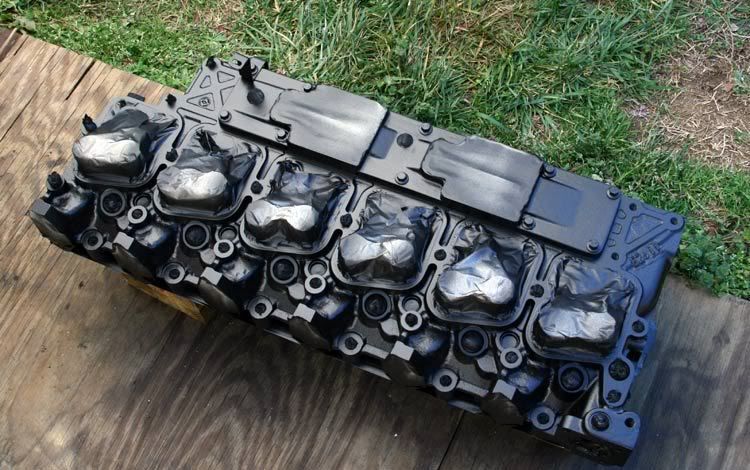
In this picture what is the reason for the difference in the colors inside the intake plenum at the rear cylinders. Do the rear cylinders run hotter than the front?
Any thoughts on fabricating a tubular intake for better air flow to all cylinders? that is an awfully big hole waiting for something to go there.
Aftercooler, air chiller, Vortex tube chiller..
I would have thought you would have polished that intake air box to a smooth finish.
Jim
Been rootin around looking for an antifreeze leak. 
Did you know there's only 23 bolts and a couple of hose clamps that holds the left side of the engine on?

The right side's not as complicated (to remove).
I guess there's no way around removing the hood to get the head off with a boom on a tractor.
Otherwise, I think this is gonna be fun.
- Hot-rod high-boost mega-ported O-Ringed head.
- 12mm studs.
- Predictive maintenance replacement of the engine oil cooler.
- Bunch of gaskets and seals.
- Stripping and repainting all the stuff.
I'll most likely drag it out over a week or so. Should be able to come up with a couple or four of "How-To's" along the way.
Did you know there's only 23 bolts and a couple of hose clamps that holds the left side of the engine on?
The right side's not as complicated (to remove).
I guess there's no way around removing the hood to get the head off with a boom on a tractor.
Otherwise, I think this is gonna be fun.
- Hot-rod high-boost mega-ported O-Ringed head.
- 12mm studs.
- Predictive maintenance replacement of the engine oil cooler.
- Bunch of gaskets and seals.
- Stripping and repainting all the stuff.
I'll most likely drag it out over a week or so. Should be able to come up with a couple or four of "How-To's" along the way.
02-28-2008, 11:33 PM
#18
1st Generation Admin
Thread Starter
I have seen these at our local Napa but I am not sure how they would work for the engine but they would at least might save the radiator. Yup, electrolysis. In addition to the sacrificial anodes, it's common practice that in water chiller HVAC systems, to have all the major components electrically bonded to one another as an additional means of combating electrolysis related corrosion as such. The dissimilar metals in contact with the water that is most often flavored with all sorts of dissolved chemicals, metals, etc. It acts as a electrolyte somewhat. Two poles (dissimilar metals) + electrolyte = battery. Short the two poles = dead short.
When I worked on Cummins engines in transit coaches they all had what was called a Perry Filter. It was a small tank that was plumbed into the cooling system as a bypass and inside of it was a sock that contained Zinc Chromate and below the sock was a Zinc anode, the coolant was pee yellow. In all of the years I have worked on then I do not ever remember seeing corrosion as being an issue in them, the engines had millions of miles on them. I�ll admit these were wet sleeve engines.
Some of the old timer mechanics would muck up the works when their ideas was to add machinist milk to the mix. and I think that lowers the effency of the coolant. The machinists milk more than likely did contribute to better control of corrosion due to it's filming qualities. But that in itself has a down-side. That being all films are to one degree or another, something of an insulator when it comes to heat transfer. DOH!!
And lot of the destruction can come from electrolysis. Anyone who has had to repair a cheap copper repipe job will have seen this.
Your engine is looking nice, How are the A/C lines where they get close to the turbo from the heat? Thanks Jim. The refrigeration line-set doesn't present with any outwardly apparent problems. No doubt it's stiffer than new so I haven't been testing it's limits. Knock on wood, It's all OEM less I remember doing a refrigerant circuit dehydration and recharge a few years ago as a PM thing. It's been a good reliable system.
Man I could not imagine having to work on anything when it is that cold, a freezing winter for me is 60* It's irritating the crap out of me! 20 years ago I could hang up-side down in the engine bay with it 20*F all night long. Tonight I came home and went to bed.
When I worked on Cummins engines in transit coaches they all had what was called a Perry Filter. It was a small tank that was plumbed into the cooling system as a bypass and inside of it was a sock that contained Zinc Chromate and below the sock was a Zinc anode, the coolant was pee yellow. In all of the years I have worked on then I do not ever remember seeing corrosion as being an issue in them, the engines had millions of miles on them. I�ll admit these were wet sleeve engines.
Some of the old timer mechanics would muck up the works when their ideas was to add machinist milk to the mix. and I think that lowers the effency of the coolant. The machinists milk more than likely did contribute to better control of corrosion due to it's filming qualities. But that in itself has a down-side. That being all films are to one degree or another, something of an insulator when it comes to heat transfer. DOH!!
And lot of the destruction can come from electrolysis. Anyone who has had to repair a cheap copper repipe job will have seen this.
Your engine is looking nice, How are the A/C lines where they get close to the turbo from the heat? Thanks Jim.
The refrigeration line-set doesn't present with any outwardly apparent problems. No doubt it's stiffer than new so I haven't been testing it's limits. Knock on wood, It's all OEM less I remember doing a refrigerant circuit dehydration and recharge a few years ago as a PM thing. It's been a good reliable system.Man I could not imagine having to work on anything when it is that cold, a freezing winter for me is 60* It's irritating the crap out of me! 20 years ago I could hang up-side down in the engine bay with it 20*F all night long. Tonight I came home and went to bed.
David,
In this picture what is the reason for the difference in the colors inside the intake plenum at the rear cylinders. Do the rear cylinders run hotter than the front? I've been thunkin on that. . . . . not sure . . . Combustion temperature variations? Years of less than equal air flow (with it's associated cooling effects)? Water/Meth wash? I initially ran windshield washer fluid. Soap bubbles?
I've thought about painting the interior of the new head. Seeing as under normal design operating conditions, there's only air flowing through there. A coating of silver (flake aluminum) paint would not only aid in preventing common corrosion of the iron (not that it's a real issue), it would also contribute to lessening reheating of the charge-air albeit a small contribution. Or so it seems in my head. Proper selection of the paint should prove something durable to the occasional W/M. We'll see.
Any thoughts on fabricating a tubular intake for better air flow to all cylinders? that is an awfully big hole waiting for something to go there.
After-cooler, air chiller, Vortex tube chiller.. Through the years it seems there's been a few proto-type/custom tubular intakes built. Seems there's a blue painted image of one floating around the Internet. I don't know that the benefits considering it's a forced induction engine made it's costs justifiable. The CTD is standardly equipped with an air/water heat exchanger that mounts there. A lot of busses run with them. The charge-air side of things is plumbed just like the Dodge's air/air heat exchanger. There's a few folks around these forums who prefer them over the more traditional air/air exchanger. I've often thought that if one could work out the pipe routing/space issues, it'd be a great, true inter-cooler for a twin setup. Primary Turbo > Water-side Inter-cooler > Secondary Turbo > Air-side after-cooler (the one up front of the radiator).
ZZ-Fabrications (?) sells a custom aluminum remake of the OEM intake log found on the CTD. Saw off the OEM section of the head and bolt theirs on. It basically duplicates what's already there. The real benefit is that sawing off the OEM allows direct access to that pesky number one intake runner for a proper porting job. That three bolt boss at the front of the OEM intake log has one of the bosses well into the flow pattern ~
I've thought of a refrigerant heat exchanger there. Seems I recall Banks had a water-side heat exchanger mounted under a big fat blower on one of their racing big-blocks. They're all the same in function. Cooler charge-air is denser charge-air.
For now, I've got the Twin-Ram intake air-horn.
I would have thought you would have polished that intake air box to a smooth finish. If it were naturally aspirated, maybe. I think the aluminum leaf silver paint might be the thing to do.
In this picture what is the reason for the difference in the colors inside the intake plenum at the rear cylinders. Do the rear cylinders run hotter than the front? I've been thunkin on that. . . . . not sure . . . Combustion temperature variations? Years of less than equal air flow (with it's associated cooling effects)? Water/Meth wash? I initially ran windshield washer fluid. Soap bubbles?
I've thought about painting the interior of the new head. Seeing as under normal design operating conditions, there's only air flowing through there. A coating of silver (flake aluminum) paint would not only aid in preventing common corrosion of the iron (not that it's a real issue), it would also contribute to lessening reheating of the charge-air albeit a small contribution. Or so it seems in my head. Proper selection of the paint should prove something durable to the occasional W/M. We'll see.
Any thoughts on fabricating a tubular intake for better air flow to all cylinders? that is an awfully big hole waiting for something to go there.
After-cooler, air chiller, Vortex tube chiller..
Through the years it seems there's been a few proto-type/custom tubular intakes built. Seems there's a blue painted image of one floating around the Internet. I don't know that the benefits considering it's a forced induction engine made it's costs justifiable. The CTD is standardly equipped with an air/water heat exchanger that mounts there. A lot of busses run with them. The charge-air side of things is plumbed just like the Dodge's air/air heat exchanger. There's a few folks around these forums who prefer them over the more traditional air/air exchanger. I've often thought that if one could work out the pipe routing/space issues, it'd be a great, true inter-cooler for a twin setup. Primary Turbo > Water-side Inter-cooler > Secondary Turbo > Air-side after-cooler (the one up front of the radiator).ZZ-Fabrications (?) sells a custom aluminum remake of the OEM intake log found on the CTD. Saw off the OEM section of the head and bolt theirs on. It basically duplicates what's already there. The real benefit is that sawing off the OEM allows direct access to that pesky number one intake runner for a proper porting job. That three bolt boss at the front of the OEM intake log has one of the bosses well into the flow pattern ~
I've thought of a refrigerant heat exchanger there. Seems I recall Banks had a water-side heat exchanger mounted under a big fat blower on one of their racing big-blocks. They're all the same in function. Cooler charge-air is denser charge-air.
For now, I've got the Twin-Ram intake air-horn.
I would have thought you would have polished that intake air box to a smooth finish. If it were naturally aspirated, maybe. I think the aluminum leaf silver paint might be the thing to do.
03-02-2008, 08:26 PM
#19
1st Generation Admin
Thread Starter
It goes on . . . ..
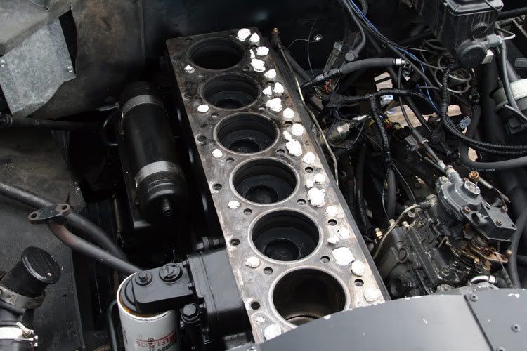
I finally got the head off ~
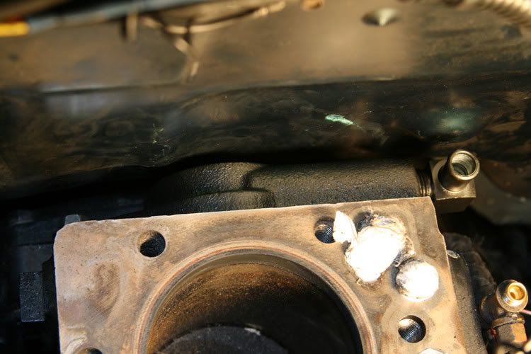
Got the initial scrapping of the old head gasket remnants done. I found where that pesky head/block leak was coming from . . . The very front/left corner of the gasket interface. Things look good otherwise ~
Bottom-tapped all the head bolt holes . . . .
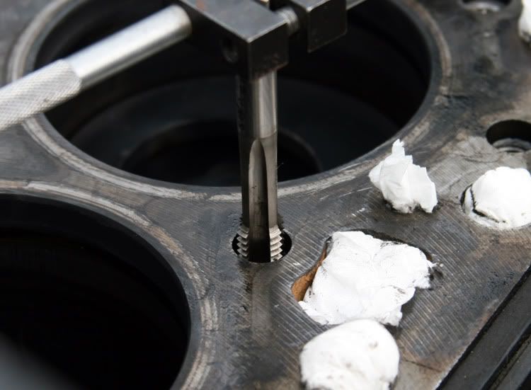
Then, using a wet/dry vacuum combined with brake cleaner flushing, I slurped the old crusty's and metal chips out. I'll do this again before installing the studs. ~
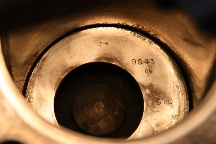
Like most others who've pulled a high mileage CTD head, the cylinder walls still present with the factory cross-hatch pattern. I was able to easily wipe away the carbon from the top of the piston using only a soft cotton towel. I'm surprised with the amount of sideways movement the piston can make in the bore. Looking down the walls, it sure looks to me as though they are wavy from top to bottom (rings in the circumference) ~
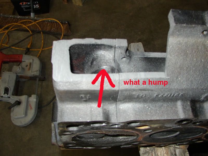
I thought this boy was near'bout ready to install when it finally happened . . . .
SURPRISE!! What's missing in this picture?
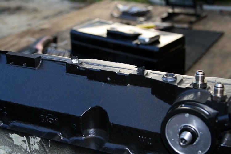
Here's a hint . . . .
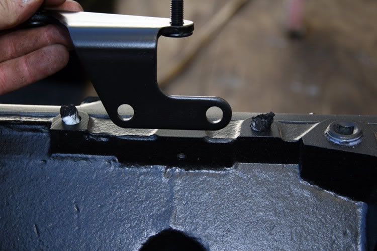
The dag'gum threaded holes for mounting the throttle bracket are missing. The boss is indeed cast into the head, just no machining, drilling and tapping.")
Three steps forward, one step backward.
I finally got the head off ~
Got the initial scrapping of the old head gasket remnants done. I found where that pesky head/block leak was coming from . . . The very front/left corner of the gasket interface. Things look good otherwise ~
Bottom-tapped all the head bolt holes . . . .
Then, using a wet/dry vacuum combined with brake cleaner flushing, I slurped the old crusty's and metal chips out. I'll do this again before installing the studs. ~
Like most others who've pulled a high mileage CTD head, the cylinder walls still present with the factory cross-hatch pattern. I was able to easily wipe away the carbon from the top of the piston using only a soft cotton towel. I'm surprised with the amount of sideways movement the piston can make in the bore. Looking down the walls, it sure looks to me as though they are wavy from top to bottom (rings in the circumference) ~
I thought this boy was near'bout ready to install when it finally happened . . . .
SURPRISE!! What's missing in this picture?
Here's a hint . . . .
The dag'gum threaded holes for mounting the throttle bracket are missing. The boss is indeed cast into the head, just no machining, drilling and tapping.
Three steps forward, one step backward.
03-02-2008, 08:27 PM
#20
1st Generation Admin
Thread Starter
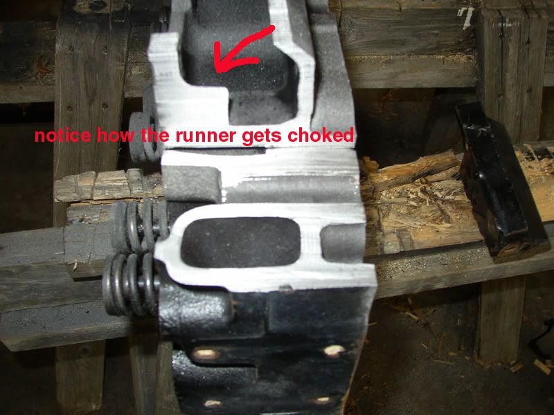
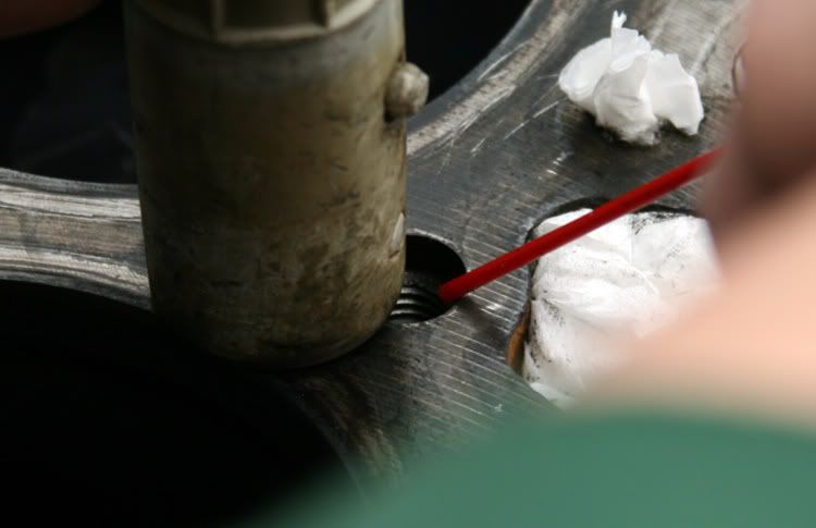
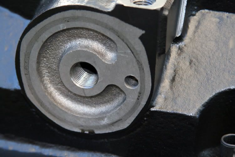
Those of you who fret over fuel flow may find this interesting ... . .
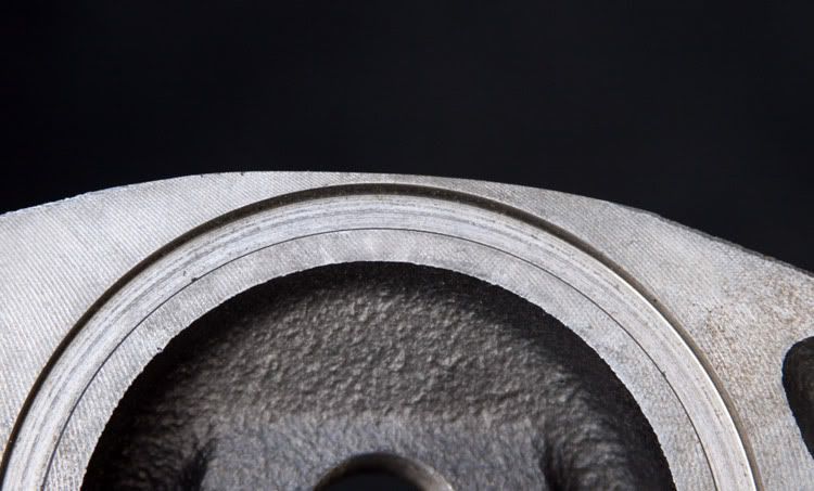
Where the fuel from the lift pump enters the head on it's way to the fuel heater (See Red Dot), the fuel first flows through a short passage on it's way to the heater itself. That little hole is only 15/32"+/- in inside diameter (See Red Arrow). It connects the much larger initial bore into the head, to the top of the fuel heater itself. Kinda small when you consider the efforts put into a big fuel line upgrade. Granted, in my case, the AN6 fittings neck down to a little over 1/4" in inside diameter, but still . . .
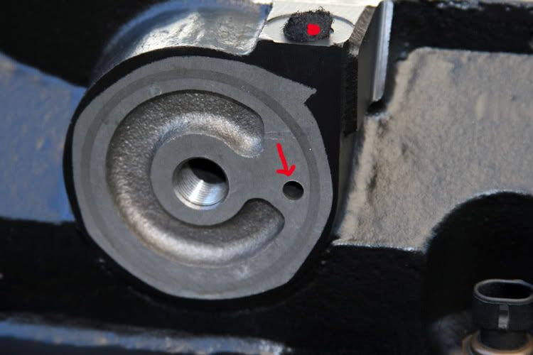
I drilled it out to 5/16" (notice the diesel fuel ring printed with the fuel heater assembly's O-ring. I used that as a guide as to how big is big enough) ~
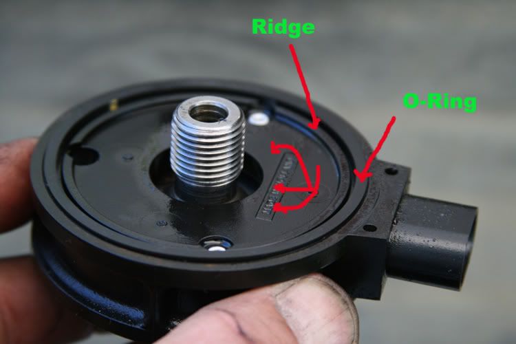
Further, notice how close the heater's top surface is to the assembly's installed height. Just inside the square-cut O-ring, that little ridge. That ridge amounts to all the space the fuel gets to flow from that hole in the head over to the heater's inlet (large hole centered in black heater housing). ~
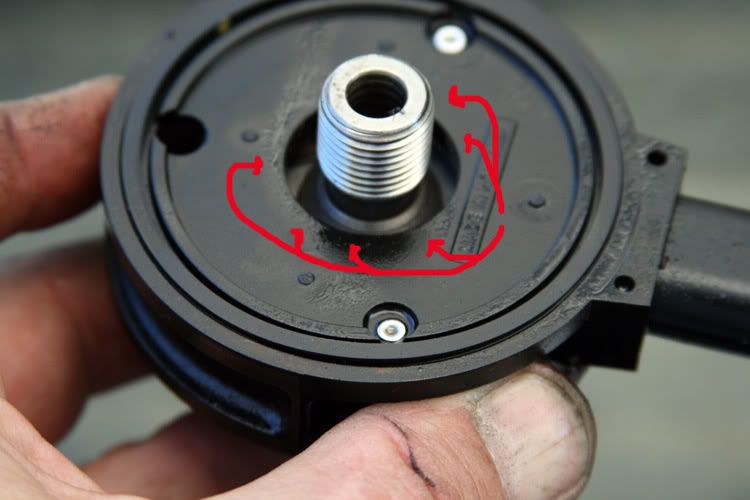
Now take note of how big that center boss is. That's where the heated, filtered fuel flows back into the head on it's way to the IP. ~

Remembering that small space allowed by the heater's ridge, there's not a whole lot of room left for the fuel to flow into the heater. ~
I ground a notch into the iron next to the now enlarged inlet so the fuel can flow less impeded into the channel cast into the head. I also knocked down that big boss such that the fuel can then flow into the heater with much less restriction. ~
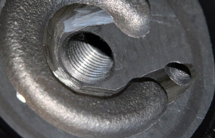
It's ugly as a rock, but it ought'a work. We'll see . . . . .
For now, I've got to:
- Drill and tap some holes to mount the throttle bracket.
- Re-wrap the OEM wiring harness where all that's come un-glued.
- Install the rear block coolant adapter thingy. I may have to dent the cab firewall a tinsy-wincy bit so as to accommodate it. I've already sanded the block there so it won't leak. Getting that freeze plug out is gonna be a blast. Can you say "Tight Fit"?
- Verify TDC.
- Lift the cab so I can get the the head to clear the studs.
- Final scouring of the block surface and flushing of the stud holes.
- Replacing the OEM side cover's gasket is gonna have to wait. The IP's in the way. It doesn't leak so that's OK.
- Put it all back together.
So far, so good.
Where the fuel from the lift pump enters the head on it's way to the fuel heater (See Red Dot), the fuel first flows through a short passage on it's way to the heater itself. That little hole is only 15/32"+/- in inside diameter (See Red Arrow). It connects the much larger initial bore into the head, to the top of the fuel heater itself. Kinda small when you consider the efforts put into a big fuel line upgrade. Granted, in my case, the AN6 fittings neck down to a little over 1/4" in inside diameter, but still . . .
I drilled it out to 5/16" (notice the diesel fuel ring printed with the fuel heater assembly's O-ring. I used that as a guide as to how big is big enough) ~
Further, notice how close the heater's top surface is to the assembly's installed height. Just inside the square-cut O-ring, that little ridge. That ridge amounts to all the space the fuel gets to flow from that hole in the head over to the heater's inlet (large hole centered in black heater housing). ~
Now take note of how big that center boss is. That's where the heated, filtered fuel flows back into the head on it's way to the IP. ~
Remembering that small space allowed by the heater's ridge, there's not a whole lot of room left for the fuel to flow into the heater. ~
I ground a notch into the iron next to the now enlarged inlet so the fuel can flow less impeded into the channel cast into the head. I also knocked down that big boss such that the fuel can then flow into the heater with much less restriction. ~
It's ugly as a rock, but it ought'a work. We'll see . . . . .
For now, I've got to:
- Drill and tap some holes to mount the throttle bracket.
- Re-wrap the OEM wiring harness where all that's come un-glued.
- Install the rear block coolant adapter thingy. I may have to dent the cab firewall a tinsy-wincy bit so as to accommodate it. I've already sanded the block there so it won't leak. Getting that freeze plug out is gonna be a blast. Can you say "Tight Fit"?
- Verify TDC.
- Lift the cab so I can get the the head to clear the studs.
- Final scouring of the block surface and flushing of the stud holes.
- Replacing the OEM side cover's gasket is gonna have to wait. The IP's in the way. It doesn't leak so that's OK.
- Put it all back together.
So far, so good.
03-03-2008, 12:40 AM
#21
Registered User
Join Date: Aug 2007
Location: VICTORIA B.C.
Posts: 353
Likes: 0
Received 0 Likes
on
0 Posts
Can the studs not be installed with the head sitting on the block so you don't have to lit the cab? Just curious. All looks good and I like what you did with enlarging the fuel passages.
03-03-2008, 08:45 AM
#22
1st Generation Admin
Thread Starter
03-03-2008, 07:33 PM
#23
1st Generation Admin
Thread Starter
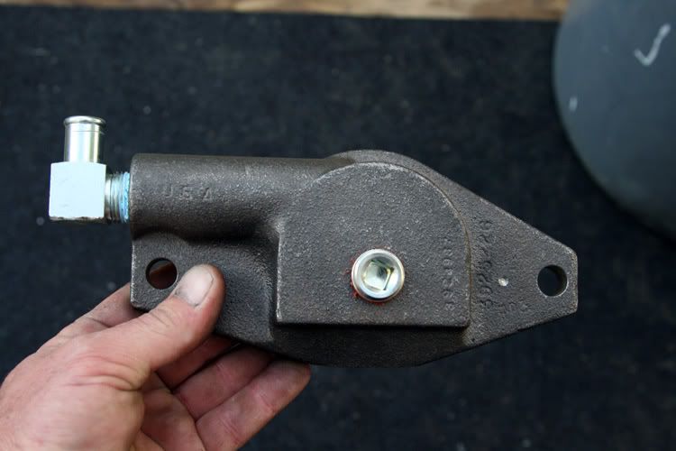
So tonight found me finishing that block coolant adjunct install. In it's OEM intended application, it takes coolant from the rear of the block and sends it to the engine mounted air compressor for cooling purposes and back to the base of the head. The pressure difference between the cylinder jacket and the head (head gasket provides the restriction/throttling/distribution) is what provides the flow in that branch of the coolant circuit.
In my application, it's gonna improve the consistency of the cylinder jacket temps as it will increase the circulation specific to that area (from the pump, through the jacket and back to the pump inlet) . I haven't nailed down exactly where I'm gonna connect the line yet.
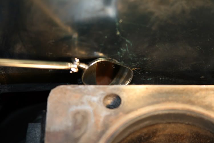
So using my trusty dental mirror, I sanded the rear of the block to remove any paint and stuff so the O-ring will seal correctly. Watch the knuckles, there's only about .75" to 1.25" to work with ~
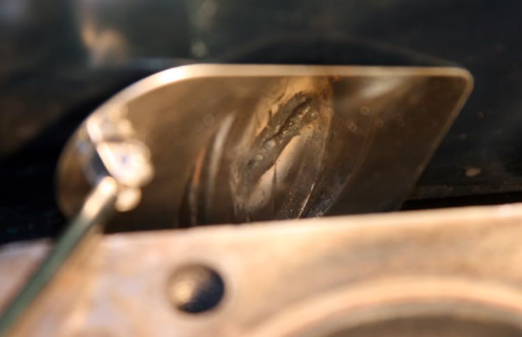
I then take my cutting torch and gouge a slice in the freeze plug and remove it. Careful of that cylinder wall! ~
Now slip the adjunct in there and bolt it down. ~
That boy's in there like a hair in a biscuit!
I've still got to verify TDC and dress the wiring harness, then on to putting the head back on.
In my application, it's gonna improve the consistency of the cylinder jacket temps as it will increase the circulation specific to that area (from the pump, through the jacket and back to the pump inlet) . I haven't nailed down exactly where I'm gonna connect the line yet.
So using my trusty dental mirror, I sanded the rear of the block to remove any paint and stuff so the O-ring will seal correctly. Watch the knuckles, there's only about .75" to 1.25" to work with ~
I then take my cutting torch and gouge a slice in the freeze plug and remove it. Careful of that cylinder wall! ~
Now slip the adjunct in there and bolt it down. ~
That boy's in there like a hair in a biscuit!
I've still got to verify TDC and dress the wiring harness, then on to putting the head back on.
03-04-2008, 09:33 AM
#26
1st Generation Admin
Thread Starter
Thanks Phil, . . . I think.
Yup, about 1/8" off the bottom round (next to my pinky finger in the image above). That still leaves just under 1/8" of meat still encasing the outside diameter of the O-ring groove. I've got pictures at the house. I'll post one later this evening.
03-04-2008, 05:55 PM
#28
1st Generation Admin
Thread Starter
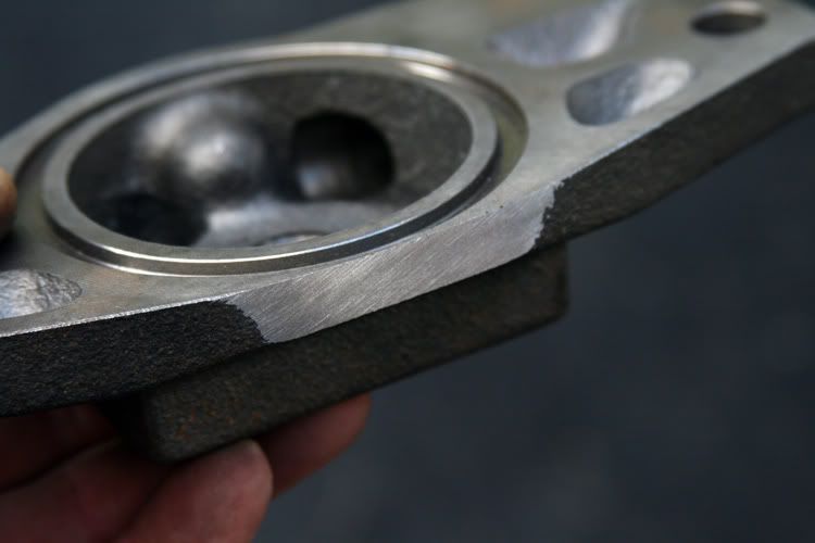
Ok, so maybe it's closer to 1/16" of meat left.
 03-05-2008, 07:23 PM
#30
1st Generation Admin
Thread Starter
Last night was stormy. Nothing done.
Tonight I drilled and tapped the new head for the throttle bracket. Assembled all that.
Got the exhaust manifold and turbo exhaust housing ready to be glass-beaded. I'll coat them once I drill the exhaust housing's volute divider wall for the waste-gate.
Still need to do the wiring harness mess, and TDC. I've not yet figured out a good way to make and install a timing pointer thingy such that it'd be dead-on in all instances. Still cypherin there.
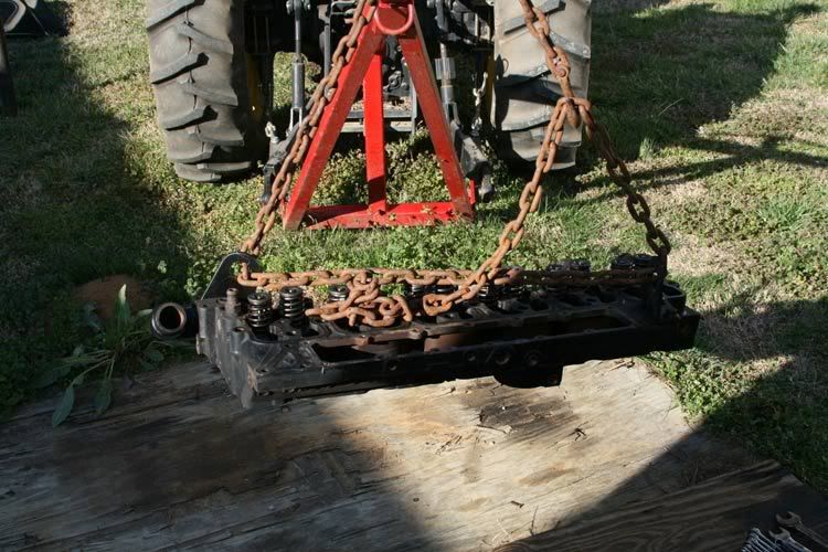
Look what I can do . . ..

Tonight I drilled and tapped the new head for the throttle bracket. Assembled all that.
Got the exhaust manifold and turbo exhaust housing ready to be glass-beaded. I'll coat them once I drill the exhaust housing's volute divider wall for the waste-gate.
Still need to do the wiring harness mess, and TDC. I've not yet figured out a good way to make and install a timing pointer thingy such that it'd be dead-on in all instances. Still cypherin there.
Look what I can do . . ..