
BC's Twin Install / AKA: "I'm Gonna Blow Up My Heap!" (updated as it occurs)
 09-24-2008, 10:08 AM
#91
1st Generation Admin
Thread Starter
You pretty-much take a deep socket that fits it and drive it home with a big honk'in hammer. I applied a little Leak-Lock for good sport.
 09-27-2008, 12:49 AM
#93
1st Generation Admin
Thread Starter
OK so this Friday evening I was able to get off work at a decent hour and get a little done . . . . .
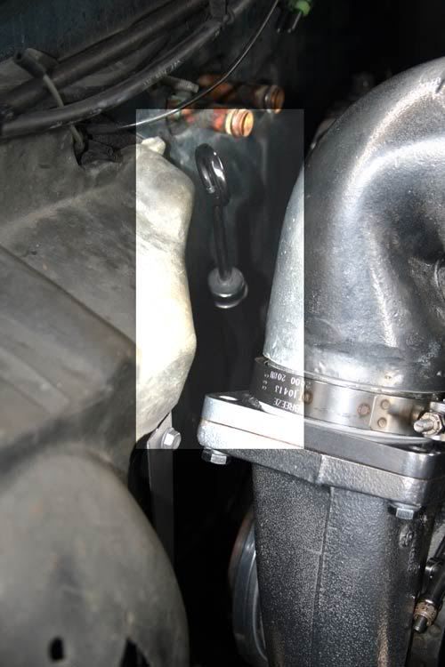
- My cypher'in has led me to believe that I'll need to get the new down-pipe installed and hooked up to both the primary's exhaust housing and the exhaust system's intermediate pipe (this is a 4x4 truck) to begin "Clocking" the Hot side of the turbochargers.
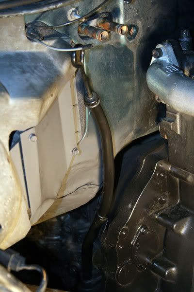
Boy-Howdy it's tight in there (this is looking up from under the truck, right there between the front drive-shaft and the right front axle spring pack). Clockwise, from 9:00 to 3:00, that's the transmission's bell-housing / adapter plate with the OEM down-pipe mount, the standing seam of the passenger's floor panel and firewall, and the right frame rail. That's the transmission dip-stick tube jutting across all of it.
Folks, I can't think of a way that one might technically describe how to make room for the new down-pipe. Suffice it to say I removed the dip-stick tube and OEM down-pipe mount. Then using space-age applications of a small floor-jack and a Big Honk'in Hammer, I moved that seam and general lower corner (if you will) of the floor panel / firewall, back and up perhaps an inch and a half. A lot of eye-balling and a couple of busted knuckles . . . .
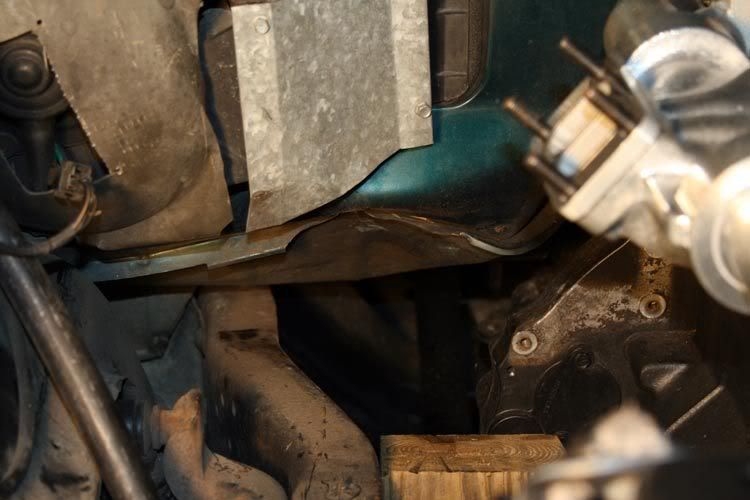
As such, I'm left with the looks of this under there . . . .
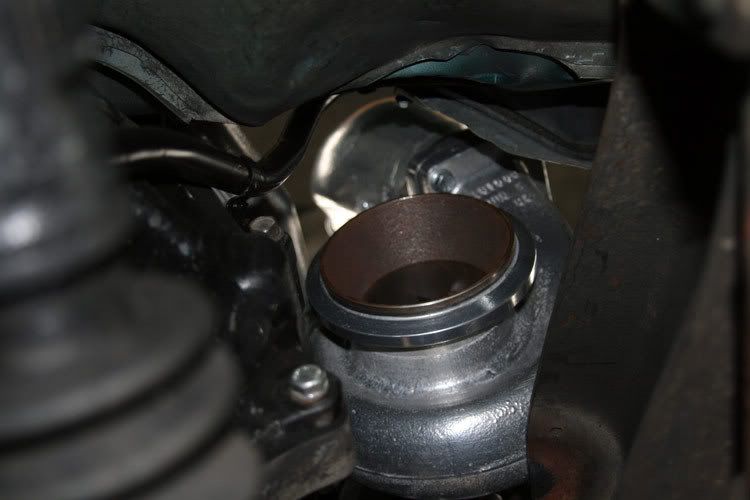
Understand the twin turbo thing had to be installed and removed one or four times to arrive at a point of acceptable clearance . . . no less than one inch between the down-pipe and firewall.
With that, I was able to pretty-much nail down the fit and location of the twin's hot-pipe stuff, down-pipe and exhaust intermediate pipe.
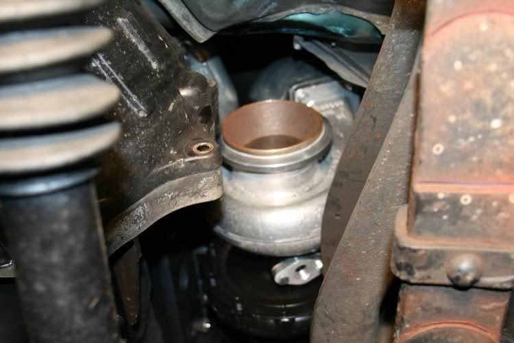
Plenty of room . . . .

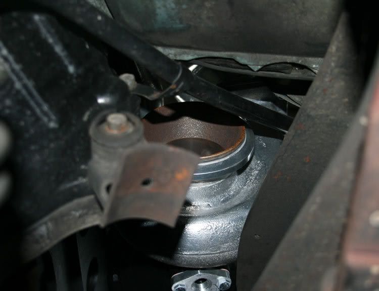
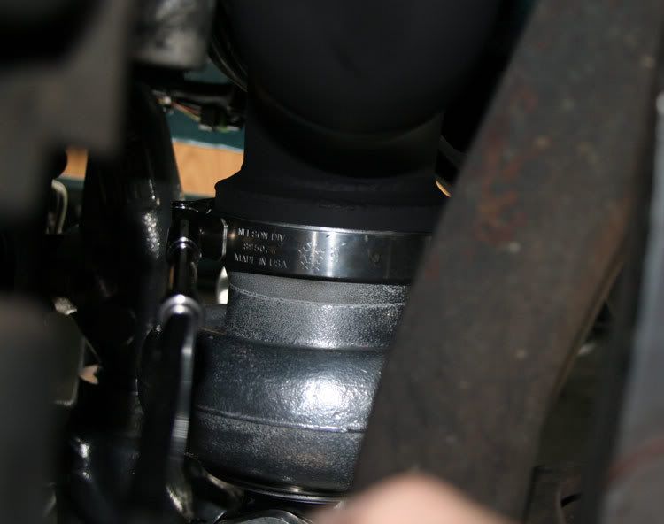
Except for right there under the primary's exhaust housing, where it passes over the passenger's frame rail. There's right at 5/16" clearance between the two. I'm thinking of notching the flange of the frame rail. No more than a quarter of an inch or so should allow enough room for the engine's torque-twist plus a bit.
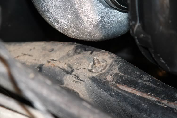
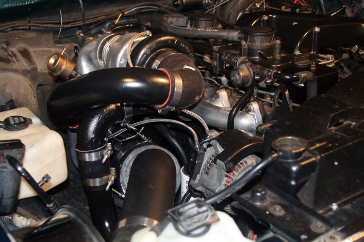
Alright, standing back and having a swallow of iced tea shows me this . . . .
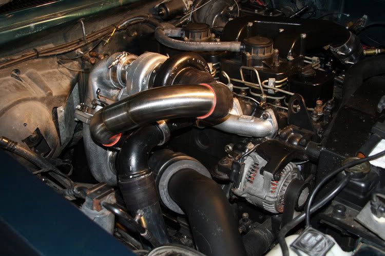
From there I loosened-up the compressor housings and began clocking them to accommodate the cold-side plumbing . . . .
Not bad for a leisure six hours including a plate of BBQ from a local church fund-raiser. I hope to begin taking care of a number of loose ends over the weekend.
. . . . . . . . getting to the short rows now.
- My cypher'in has led me to believe that I'll need to get the new down-pipe installed and hooked up to both the primary's exhaust housing and the exhaust system's intermediate pipe (this is a 4x4 truck) to begin "Clocking" the Hot side of the turbochargers.
Boy-Howdy it's tight in there (this is looking up from under the truck, right there between the front drive-shaft and the right front axle spring pack). Clockwise, from 9:00 to 3:00, that's the transmission's bell-housing / adapter plate with the OEM down-pipe mount, the standing seam of the passenger's floor panel and firewall, and the right frame rail. That's the transmission dip-stick tube jutting across all of it.
Folks, I can't think of a way that one might technically describe how to make room for the new down-pipe. Suffice it to say I removed the dip-stick tube and OEM down-pipe mount. Then using space-age applications of a small floor-jack and a Big Honk'in Hammer, I moved that seam and general lower corner (if you will) of the floor panel / firewall, back and up perhaps an inch and a half. A lot of eye-balling and a couple of busted knuckles . . . .
As such, I'm left with the looks of this under there . . . .
Understand the twin turbo thing had to be installed and removed one or four times to arrive at a point of acceptable clearance . . . no less than one inch between the down-pipe and firewall.
With that, I was able to pretty-much nail down the fit and location of the twin's hot-pipe stuff, down-pipe and exhaust intermediate pipe.
Plenty of room . . . .
Except for right there under the primary's exhaust housing, where it passes over the passenger's frame rail. There's right at 5/16" clearance between the two. I'm thinking of notching the flange of the frame rail. No more than a quarter of an inch or so should allow enough room for the engine's torque-twist plus a bit.
Alright, standing back and having a swallow of iced tea shows me this . . . .
From there I loosened-up the compressor housings and began clocking them to accommodate the cold-side plumbing . . . .
Not bad for a leisure six hours including a plate of BBQ from a local church fund-raiser. I hope to begin taking care of a number of loose ends over the weekend.
. . . . . . . . getting to the short rows now.
 09-27-2008, 11:05 AM
#95
Registered User

Lokar makes a cool braided stainless firewall mount dipstick tube that I used when I put in my 4" DP. I got mine from Summit Racing. Great write up as always!!!
 09-27-2008, 12:54 PM
#97
Registered User

Join Date: Apr 2006
Location: Crockett, CA
Posts: 650
Likes: 0
Received 0 Likes
on
0 Posts
I remember when I was fabbing up my twins and working on the downpipe... that area gets CRAZY tight on these first gens!!
Is your DP 4"? Should probably fit a little better than my 5". I had to cut and weld the floorboard THEN beat it with a hammer.
Is your DP 4"? Should probably fit a little better than my 5". I had to cut and weld the floorboard THEN beat it with a hammer.
09-27-2008, 02:28 PM
#98
1st Generation Admin
Thread Starter


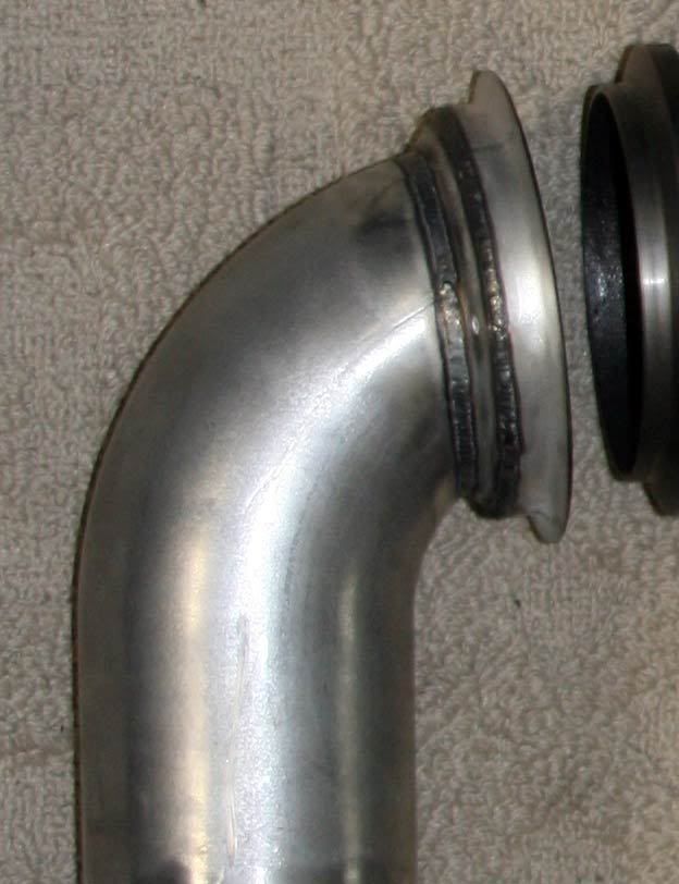
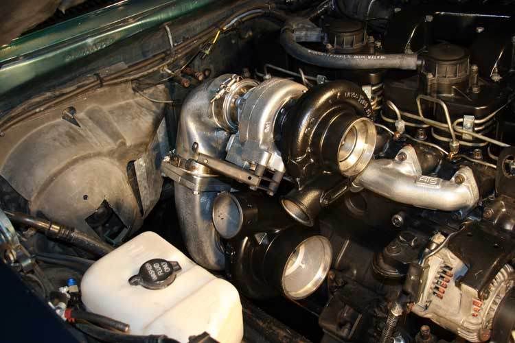
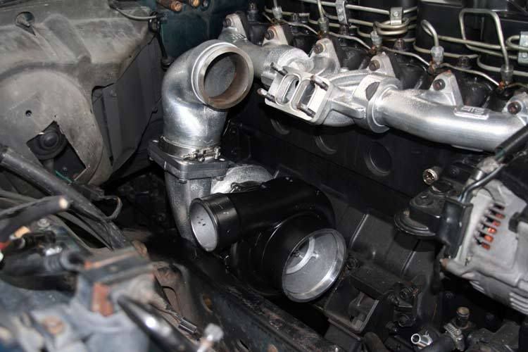
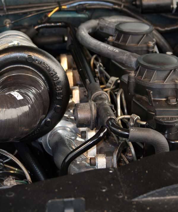
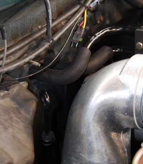
One thing that I must point out is the way this particular hot-pipe is made. Notice how it's shaped kinda like a backward question mark (work with me
 ).
). 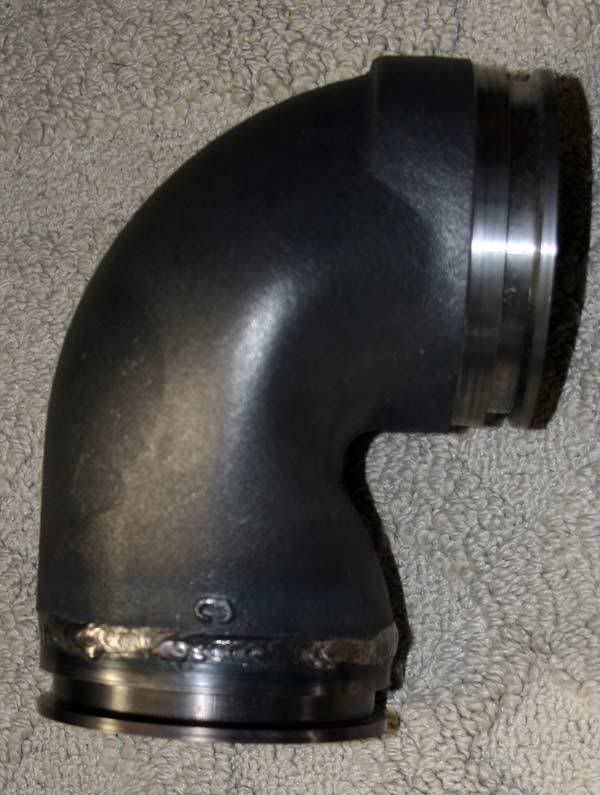
Compare that to what might be called the typical unit made with a standard 90* Ell.
This hot-pipe will place the primary well forward of what that made with a regular 90* Ell meaning I'd have to move a LOT less landscape for the down-pipe.
 I didn't want to cut up the floorboard.
Certainly, things are there AT the oil filter! There just is room but it'll work just fine.
Again, thanks for the kind words y'all.
I've been screwing around so far this morning, time to get to it . . . .
 09-30-2008, 10:18 PM
#101
1st Generation Admin
Thread Starter
I've gotten a little more done over the past couple of days . . . .
Using a Shoe & Die type pipe bender, I put a few more subtle curves in the Transmission dip-stick tube. Pretty much 3/4" give or take from the firewall.
OK, so this "Twins" thing . . . . . baring all the other crap I've incorporated in this job, the installation of the twin system is rather straight forward. Having completed some sub-assembly . . . .
- Attach the exhaust manifold to the head. It's mounted upside down so as to allow more room up under for the new Primary turbocharger (HT3B).
- Place a 1/2" spacer on the exhaust manifold with a couple of gaskets. This gives some room for the Secondary turbocharger's (HX35-hybrid) compressor housing to clear the manifold.
- Be sure the bolts for the primary turbocharger's compressor and exhaust housing are loose as well as the down-pipe/adapter band-clamps for later "Clocking".
- Place the Primary turbocharger and Hot-Pipe sub-assembly on the frame rail. This is because once the secondary turbocharger is installed, moving the primary into place is a bit of a chore for the lack of room.
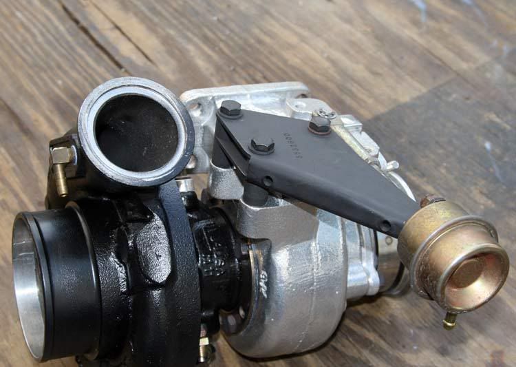
I used some compressed nitrogen gas to set the secondary's waste-gate actuator to begin opening at 26psig. I did it by adjusting the length of the actuator rod.
- Loosen the secondary turbocharger's exhaust housing bolts for later clocking.
- Now bolt the secondary turbocharger assembly into place.
- Eat some spinach.
- Lift the primary turbocharger / Hot-pipe assembly and attach it to the secondary turbocharger's exhaust outlet.
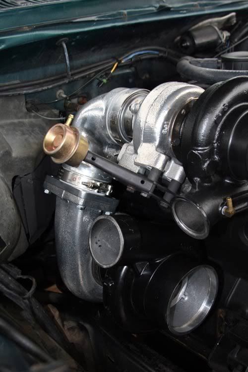
Talking about the transmission dip-stick tube . . . . as bent, there's about 1.5" (+/-) between it and the hot-pipe.
From under the truck, you can see there's reasonable room left for the exhaust down-pipe.
-While you're under there, go ahead and mount the down-pipe with it's band-clamp. Leave it loose for clocking.
- From there, you've got to wiggle things around so that the turbocharger's and down-pipe are positioned such that nothing can touch/rub/dent/bend anything during the normal use of the truck. Don't get in a hurry.
- Make sure the turbocharger's oil drains are pointing down.
- Now tighten the exhaust housing bolts and band-clamps for the hot-pipe and down-pipe.
- Trial fit the cold-pipe stuff so that you can clock turbocharger's compressor housings and blot them down.
- > You may have to readjust everything a couple or thirty times to get everything to line-up satisfactorily.
From that point, you'll start on the turbocharger oil supply lines, the secondary oil drain hose, etc. Don't get in a hurry and install the air filter feed-pipe just yet as it'll be in the way.
As ironic as it may sound, I really do want to maintain something of a "Factory Look" if not function. The cab heat plumbing took a few minutes of cypher'in. The OEM location of the cab heat hot-water valve would have it up against the hot-pipe. So I moved it. I pretty-much chopped-up the OEM tubing for the cab heat and transmission heat exchanger, swaged and brazed the pieces and came up with this . . .
I'll need to extend the vacuum line for the valve. No big deal.
At the firewall end of things, I fashioned the pipes so they'd be right there at the wall and turn immediately to the heater core. All no closer than a couple of inches from the hot-pipe. The "Kit" I'm using for all of this came with some of that 1" fiberglass wrap. I may just cover that back there for some additional protection from heat.
. . . . Using a Shoe & Die type pipe bender, I put a few more subtle curves in the Transmission dip-stick tube. Pretty much 3/4" give or take from the firewall.
OK, so this "Twins" thing . . . . . baring all the other crap I've incorporated in this job, the installation of the twin system is rather straight forward. Having completed some sub-assembly . . . .
- Attach the exhaust manifold to the head. It's mounted upside down so as to allow more room up under for the new Primary turbocharger (HT3B).
- Place a 1/2" spacer on the exhaust manifold with a couple of gaskets. This gives some room for the Secondary turbocharger's (HX35-hybrid) compressor housing to clear the manifold.
- Be sure the bolts for the primary turbocharger's compressor and exhaust housing are loose as well as the down-pipe/adapter band-clamps for later "Clocking".
- Place the Primary turbocharger and Hot-Pipe sub-assembly on the frame rail. This is because once the secondary turbocharger is installed, moving the primary into place is a bit of a chore for the lack of room.
I used some compressed nitrogen gas to set the secondary's waste-gate actuator to begin opening at 26psig. I did it by adjusting the length of the actuator rod.
- Loosen the secondary turbocharger's exhaust housing bolts for later clocking.
- Now bolt the secondary turbocharger assembly into place.
- Eat some spinach.
- Lift the primary turbocharger / Hot-pipe assembly and attach it to the secondary turbocharger's exhaust outlet.
Talking about the transmission dip-stick tube . . . . as bent, there's about 1.5" (+/-) between it and the hot-pipe.
From under the truck, you can see there's reasonable room left for the exhaust down-pipe.
-While you're under there, go ahead and mount the down-pipe with it's band-clamp. Leave it loose for clocking.
- From there, you've got to wiggle things around so that the turbocharger's and down-pipe are positioned such that nothing can touch/rub/dent/bend anything during the normal use of the truck. Don't get in a hurry.
- Make sure the turbocharger's oil drains are pointing down.
- Now tighten the exhaust housing bolts and band-clamps for the hot-pipe and down-pipe.
- Trial fit the cold-pipe stuff so that you can clock turbocharger's compressor housings and blot them down.
- > You may have to readjust everything a couple or thirty times to get everything to line-up satisfactorily.
From that point, you'll start on the turbocharger oil supply lines, the secondary oil drain hose, etc. Don't get in a hurry and install the air filter feed-pipe just yet as it'll be in the way.
As ironic as it may sound, I really do want to maintain something of a "Factory Look" if not function. The cab heat plumbing took a few minutes of cypher'in. The OEM location of the cab heat hot-water valve would have it up against the hot-pipe. So I moved it. I pretty-much chopped-up the OEM tubing for the cab heat and transmission heat exchanger, swaged and brazed the pieces and came up with this . . .
I'll need to extend the vacuum line for the valve. No big deal.
At the firewall end of things, I fashioned the pipes so they'd be right there at the wall and turn immediately to the heater core. All no closer than a couple of inches from the hot-pipe. The "Kit" I'm using for all of this came with some of that 1" fiberglass wrap. I may just cover that back there for some additional protection from heat.
09-30-2008, 10:19 PM
#102
1st Generation Admin
Thread Starter
It won't be long now . . . .
I've still got to;
- Pull some slack pyrometer probe cable out of the dash so I can run it over to the new probe location without it getting burnt.
- Hook-up the waste-gate control reference tube (I've been incorporating the water/methanol controller with it).
- Run the cab heat water valve vacuum line.
- Fabricate and install the primary turbocharger's support brace . . . . that ought to be a hoot.
- With the support bracket in place, I can install the primary's oil drain hose.
- Install the muffler and tail-pipe assembly.
- Reinstall the saved transmission fluid and engine coolant.
Then figure out what I've forgotten . . . .. . . .
10-02-2008, 10:03 AM
#104
Registered User
Great job David.
I just want to clarify a few things. David is going above and beyond on this install. You have to hand it to him as he is doing an unreal job, but I just wanted to point out, you do not have to relocate the water vacuum diagram or notch the frame in any way. Nor do you have to mess with the fire wall rubber cover. The transmission/coolant heat exchanger is also an option and doesn't need to be relocated, as you can simply remove it. I have run without one on my old 93 with towing and hot and very cold weather, running up to 700hp for years without any problems. I designed this kit to be as simple as possible and to be installed with simple hand tools. A welder would come in handy for the bottom turbo support, but the customer can simply bend some flat bar and drill some support holes in it to bolt to the Primary charger and motor mount, engine or adapter plate depending on the trucks configuration.
I just want to clarify a few things. David is going above and beyond on this install. You have to hand it to him as he is doing an unreal job, but I just wanted to point out, you do not have to relocate the water vacuum diagram or notch the frame in any way. Nor do you have to mess with the fire wall rubber cover. The transmission/coolant heat exchanger is also an option and doesn't need to be relocated, as you can simply remove it. I have run without one on my old 93 with towing and hot and very cold weather, running up to 700hp for years without any problems. I designed this kit to be as simple as possible and to be installed with simple hand tools. A welder would come in handy for the bottom turbo support, but the customer can simply bend some flat bar and drill some support holes in it to bolt to the Primary charger and motor mount, engine or adapter plate depending on the trucks configuration.
10-02-2008, 10:18 AM
#105
Registered User
Join Date: Aug 2006
Location: Cresson/Stephenville Texas
Posts: 2,436
Likes: 0
Received 0 Likes
on
0 Posts
Great job David.
I just want to clarify a few things. David is going above and beyond on this install. You have to hand it to him as he is doing an unreal job, but I just wanted to point out, you do not have to relocate the water vacuum diagram or notch the frame in any way. Nor do you have to mess with the fire wall rubber cover. The transmission/coolant heat exchanger is also an option and doesn't need to be relocated, as you can simply remove it. I have run without one on my old 93 with towing and hot and very cold weather, running up to 700hp for years without any problems. I designed this kit to be as simple as possible and to be installed with simple hand tools. A welder would come in handy for the bottom turbo support, but the customer can simply bend some flat bar and drill some support holes in it to bolt to the Primary charger and motor mount, engine or adapter plate depending on the trucks configuration.
I just want to clarify a few things. David is going above and beyond on this install. You have to hand it to him as he is doing an unreal job, but I just wanted to point out, you do not have to relocate the water vacuum diagram or notch the frame in any way. Nor do you have to mess with the fire wall rubber cover. The transmission/coolant heat exchanger is also an option and doesn't need to be relocated, as you can simply remove it. I have run without one on my old 93 with towing and hot and very cold weather, running up to 700hp for years without any problems. I designed this kit to be as simple as possible and to be installed with simple hand tools. A welder would come in handy for the bottom turbo support, but the customer can simply bend some flat bar and drill some support holes in it to bolt to the Primary charger and motor mount, engine or adapter plate depending on the trucks configuration.