
BC's Twin Install / AKA: "I'm Gonna Blow Up My Heap!" (updated as it occurs)
 09-15-2008, 10:55 PM
#76
1st Generation Admin
Thread Starter
A little update.
It's been slow, had a couple of obstacles . .. the remnants of at least one hurricane mixed in with a lot of much needed rain. Had to rebuild the steering of the mower . . . . lost the truck once in the yard once.
Oh! And then the hot water heater sprung a leak up top in its supply line.
Regarding the transmission stuff;
- Completed the fabrication and installation of the auxiliary cooler's fan control. A two position switch (Auto/Manual On) in the cab works a 30amp relay mounted at the cooler. I can select either ON, or have the fluid thermostat run it automatically. The relay in turn applies power to the fan. There's an LED fed from the fan's power line to indicate the fans status. The control circuit is ignition switch powered. Over all, it should get Jim Lane's nod.
- Less connecting the return line to the engine coolant pump inlet, I've got the water side plumbing of the trans fluid heat exchanger installed. It includes a 1/4 turn ball valve to stop hot engine coolant flow when racing.
- Completed the transmission fluid's plumbing using 1/2" ID hose with AN8 fittings through out.
- The auxiliary cooler and heat exchanger/filter sub-assemblies have been painted and bolted into place.
Regarding the turbo stuff;
- JetHot corrected the areas of the hot-pipe they missed.
- The secondary turbo (HX35 hybrid) exhaust housing (14cm) ~ the waste-gate chamber's lid, radiused the sharp edge right there where the exhaust gases come out and turn into the exhaust outlet. Again using the die-grinder, enlarged and sorta port matched (if you will) the opening under the waste-gate flapper itself.
- The spacer plate that goes between the exhaust manifold and the secondary exhaust housing, it apparently is sized (internal holes) for an exhaust housing with a bigger inlet than that of the Holset 14cm unit . . . . . maybe? It matches the gasket perfectly.
They're bigger than the outlet holes of the ATS manifold for that matter. Kind of a large "pot-hole" in the road of airflow in my mind.
Rather than potentially messing up gas velocities and possible future top turbo upgrades, I opted to simply radius the top turbos exhaust housing inlets to soften said "pot-holes" bump. I suppose it could now be seen as something of an "Anti-reversion dam".
- Got a base coat of paint on both turbocharger's center sections as well as the compressor housings.
With that, I'm fast running out of excuses to get on with hanging the hair driers.
I'm on-call with work this week, and it's suppose to rain the next day or so. We'll see.
 09-16-2008, 01:44 PM
#77
Registered User
Join Date: Aug 2008
Posts: 1,055
Likes: 0
Received 0 Likes
on
0 Posts
hey sorry to be off topic but does anyone no the wheel sizes of the BHT3B for this kit . i want to match up a different turbo the same . i sold the turbo i was going to use lol ....
09-21-2008, 09:57 PM
#79
1st Generation Admin
Thread Starter
Well, I've not accomplished much since my last post.  Been busy with work and real life.
I went to do another head stud re-torque this weekend and with removing all the valve covers, disconnecting the high pressure lines from the injectors and loosening the valve-train . . ..
All along, I've been doing the head stud torquing as per the A1 instructions . . 125ft/lbs with the engine HOT (not including the initial stud install).
OK, fine.
In taking with Mark of PDR (they sold me the studs), he indicated they didn't do the hot-torque as they may have had issues with possibly damaging the studs or threads, I can't remember. They torque the studs COLD to 135ft/lbs without re-lubing.
Hmmm . . . .
I figured I'd do it again cold since I had the engine right there fixing to do this twins thing.
Well, I was gonna do a "Line-Torque" and started with the stud right there at the engine coolant outlet. I backed it off about a quarter turn and began to pull it back up to 135ft/lbs. To my surprise the wrench clicked about an eighth of a turn into it. Well before the point at which I started.
Hmmm . . . . Makes me think the studs are at 125ft/lbs minimum.
I figure now it'd be best to leave them alone and do a random torque check of a few of the studs (those easily gotten to) when the engine is hot.
Crap! Now put it all back together, readjusting valves, etc . . .
Got the engine cooling fan and shroud reinstalled (from lifting the engine while messing with the oil pan).
My plan at this point is to begin assembling/installing the turbos tomorrow.
One little "Got'cha" going into it: I've found that the PDR twin turbo kit for the 1st gen does NOT include a bracket to support the primary turbo. The short version of what Marks says is that there's too many possible options pending the year and transmission to come up with one working assembly.
With the relocation of the trans fluid heat exchanger, I've now got three bolt holes on the trans adapter, and at least two on the rear of the engine mounting plate to work with. To be sure I can come up with something. The PDR version (for the 2nd gen anyway) uses what amounts to a U-bolt and clevis on a small bracket going the the trans adapter plate. It holds the down-pipe.
I'm thinking of a bar from the engine mount running back to the trans adapter plate, with an arm going over to an elongated stud. Right there on the primary turbo's oil outlet flange.
We'll see.
Still waiting on that stupid muffler!
Been busy with work and real life.I went to do another head stud re-torque this weekend and with removing all the valve covers, disconnecting the high pressure lines from the injectors and loosening the valve-train . . ..
All along, I've been doing the head stud torquing as per the A1 instructions . . 125ft/lbs with the engine HOT (not including the initial stud install).
OK, fine.
In taking with Mark of PDR (they sold me the studs), he indicated they didn't do the hot-torque as they may have had issues with possibly damaging the studs or threads, I can't remember. They torque the studs COLD to 135ft/lbs without re-lubing.
Hmmm . . . .
I figured I'd do it again cold since I had the engine right there fixing to do this twins thing.
Well, I was gonna do a "Line-Torque" and started with the stud right there at the engine coolant outlet. I backed it off about a quarter turn and began to pull it back up to 135ft/lbs. To my surprise the wrench clicked about an eighth of a turn into it. Well before the point at which I started.
Hmmm . . . . Makes me think the studs are at 125ft/lbs minimum.
I figure now it'd be best to leave them alone and do a random torque check of a few of the studs (those easily gotten to) when the engine is hot.
Crap! Now put it all back together, readjusting valves, etc . . .
Got the engine cooling fan and shroud reinstalled (from lifting the engine while messing with the oil pan).
My plan at this point is to begin assembling/installing the turbos tomorrow.
One little "Got'cha" going into it: I've found that the PDR twin turbo kit for the 1st gen does NOT include a bracket to support the primary turbo. The short version of what Marks says is that there's too many possible options pending the year and transmission to come up with one working assembly.
With the relocation of the trans fluid heat exchanger, I've now got three bolt holes on the trans adapter, and at least two on the rear of the engine mounting plate to work with. To be sure I can come up with something. The PDR version (for the 2nd gen anyway) uses what amounts to a U-bolt and clevis on a small bracket going the the trans adapter plate. It holds the down-pipe.
I'm thinking of a bar from the engine mount running back to the trans adapter plate, with an arm going over to an elongated stud. Right there on the primary turbo's oil outlet flange.
We'll see.
Still waiting on that stupid muffler!
09-22-2008, 08:36 PM
#80
1st Generation Admin
Thread Starter
Well I finally got the Bigger Honk'in Muffler in.
Donaldson M/N ~ M100944
A - Inlet Diameter (Inches): 5
B - Body Diameter (Inches): 10
D - Overall Length (Inches): 51
E - Outlet Diameter (Inches): 5
Rated Flow LR (CFM): 1765
Rated Flow MR (CFM): 2494
Rated Flow HR (CFM): 2950
Back Press LR (In Hg): 1
Back Press MR (In Hg): 2
Back Press HR (In Hg): 3
Attenuation (dBA): 16-23 (Relatively quiet)
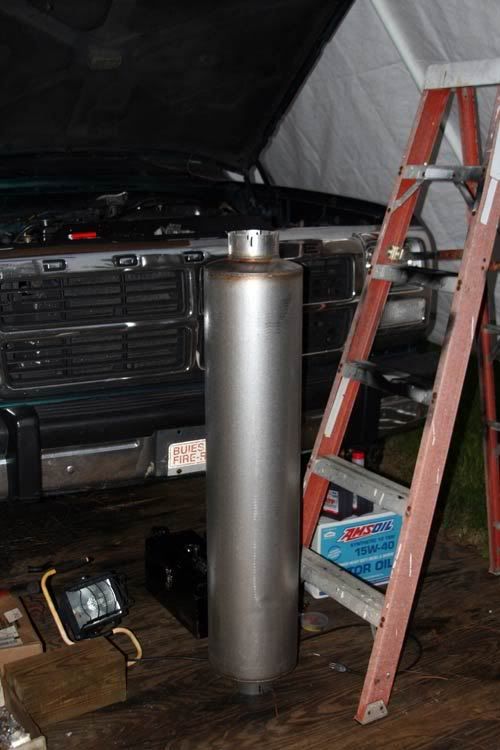
With that in-hand, I've been able to cypher the plumbing to get the exhaust over and out past the rear axle. That should be here early next week.
Comparatively speaking, everything else should go pretty quick.
We'll see.")
Donaldson M/N ~ M100944
A - Inlet Diameter (Inches): 5
B - Body Diameter (Inches): 10
D - Overall Length (Inches): 51
E - Outlet Diameter (Inches): 5
Rated Flow LR (CFM): 1765
Rated Flow MR (CFM): 2494
Rated Flow HR (CFM): 2950
Back Press LR (In Hg): 1
Back Press MR (In Hg): 2
Back Press HR (In Hg): 3
Attenuation (dBA): 16-23 (Relatively quiet)
With that in-hand, I've been able to cypher the plumbing to get the exhaust over and out past the rear axle. That should be here early next week.
Comparatively speaking, everything else should go pretty quick.
We'll see.
 09-22-2008, 09:39 PM
#82
1st Generation Admin
Thread Starter
I don't believe so.
I've selected this particular muffler based primarily on it's flow capabilities closely followed by it's noise attenuation. Further, including this muffler, I've gone from 4" to 5" plumbing just past the transfer case.
While this muffler isn't quite as quiet as my last (about 3db louder), I figure the second turbo's quieting effect will make up for it.
It works on paper.
Compare for yourself.
Consider that 5" muffler one can get from AirFlo ~ http://store.airflo.com/m100465.html
If you look closely at the part number, you'll find it is a Donaldson part number. Searching Donaldson's site for it presents with this ~ https://dynamic.donaldson.com/webc/W...210&item=21887
Here's the specs ~
Here again are the specs for the one I'm fixing to install ~
The latter flows a little more and is from 1db ~ 3db quieter doing it. (A 3db increase in attenuation roughly equates to halving the apparent loudness).
Now compare that to the "High Performance" Straight-Thru 4" muffler available from AirFlo ~ http://store.airflo.com/m085171.html
In my eyes, all that amounts to a negligible difference in flow coupled with a BIG reduction in noise.
Required math ~
With the above, we're moving right at 1332 CFM through the exhaust system at 3000rpm.
NOTE: The above formula is based on a single turbocharger. As you may know, we typically see a 300*F drop in exhaust gas temperature across the turbocharger (that represents the change of thermal energy to mechanical energy). With adding a second turbocharger to the equation, we'll see a further reduction in EGT's as a result of the second charger converting even more thermal energy to mechanical energy.
With the further reduction in EGT's, the exhaust gases contract (shrink) in volume even more. With that we'll see a slight increase in CFM flow if not in density (all else being the same).
At least that's what the voices in my head say.
I've selected this particular muffler based primarily on it's flow capabilities closely followed by it's noise attenuation. Further, including this muffler, I've gone from 4" to 5" plumbing just past the transfer case.
While this muffler isn't quite as quiet as my last (about 3db louder), I figure the second turbo's quieting effect will make up for it.
It works on paper.
Compare for yourself.
Consider that 5" muffler one can get from AirFlo ~ http://store.airflo.com/m100465.html
If you look closely at the part number, you'll find it is a Donaldson part number. Searching Donaldson's site for it presents with this ~ https://dynamic.donaldson.com/webc/W...210&item=21887
Here's the specs ~
Originally Posted by M100465
A - Inlet Diameter (Inches): 5
B - Body Diameter (Inches): 10
D - Overall Length (Inches): 51
E - Outlet Diameter (Inches): 5
Rated Flow LR (CFM): 1610
Rated Flow MR (CFM): 2277
Rated Flow HR (CFM): 2790
Back Press LR (In Hg): 1
Back Press MR (In Hg): 2
Back Press HR (In Hg): 3
Attenuation (dBA): 15-20
B - Body Diameter (Inches): 10
D - Overall Length (Inches): 51
E - Outlet Diameter (Inches): 5
Rated Flow LR (CFM): 1610
Rated Flow MR (CFM): 2277
Rated Flow HR (CFM): 2790
Back Press LR (In Hg): 1
Back Press MR (In Hg): 2
Back Press HR (In Hg): 3
Attenuation (dBA): 15-20
Originally Posted by M100944
A - Inlet Diameter (Inches): 5
B - Body Diameter (Inches): 10
D - Overall Length (Inches): 51
E - Outlet Diameter (Inches): 5
Rated Flow LR (CFM): 1765
Rated Flow MR (CFM): 2494
Rated Flow HR (CFM): 2950
Back Press LR (In Hg): 1
Back Press MR (In Hg): 2
Back Press HR (In Hg): 3
Attenuation (dBA): 16-23
B - Body Diameter (Inches): 10
D - Overall Length (Inches): 51
E - Outlet Diameter (Inches): 5
Rated Flow LR (CFM): 1765
Rated Flow MR (CFM): 2494
Rated Flow HR (CFM): 2950
Back Press LR (In Hg): 1
Back Press MR (In Hg): 2
Back Press HR (In Hg): 3
Attenuation (dBA): 16-23
Now compare that to the "High Performance" Straight-Thru 4" muffler available from AirFlo ~ http://store.airflo.com/m085171.html
Originally Posted by M085171
A - Inlet Diameter (Inches): 4
B - Body Diameter (Inches): 8.5
D - Overall Length (Inches): 40
E - Outlet Diameter (Inches): 4
Rated Flow LR (CFM): 1800
Rated Flow MR (CFM): 2546
Rated Flow HR (CFM): 3119
Back Press LR (In Hg): 1
Back Press MR (In Hg): 2
Back Press HR (In Hg): 3
Attenuation (dBA): 8-12
B - Body Diameter (Inches): 8.5
D - Overall Length (Inches): 40
E - Outlet Diameter (Inches): 4
Rated Flow LR (CFM): 1800
Rated Flow MR (CFM): 2546
Rated Flow HR (CFM): 3119
Back Press LR (In Hg): 1
Back Press MR (In Hg): 2
Back Press HR (In Hg): 3
Attenuation (dBA): 8-12
In my eyes, all that amounts to a negligible difference in flow coupled with a BIG reduction in noise.
Required math ~
Code:
CFM  =  Engine Displ (cu in)  x  Full Load RPM  x  Eff  x  (Exh Temp F + 460)
                                  C  x  941760

CFM = exhaust flow rate in cubic feet per minute
Efficiency  =  .85 for naturally aspirated engines
Efficiency  =  1.4 for turbo-charged engines
Efficiency  =  1.2 for engines with scavenging blower
C  =  1 for two-cycle engine    C  =  2 for four-cycle engine

If exhaust temperature is not available, use:
T  =  1200F for gasoline engine
T  =  900F for diesel engine
With the further reduction in EGT's, the exhaust gases contract (shrink) in volume even more. With that we'll see a slight increase in CFM flow if not in density (all else being the same).
At least that's what the voices in my head say.
09-23-2008, 11:44 AM
#84
Registered User

I thought you wanted to go fast? How much does the hideous muffler weigh?
I'm still in the build it yourself camp, especially how seeing this still isn't a bolt up kit.
weigh?I'm still in the build it yourself camp, especially how seeing this still isn't a bolt up kit.
09-23-2008, 11:16 PM
#85
1st Generation Admin
Thread Starter
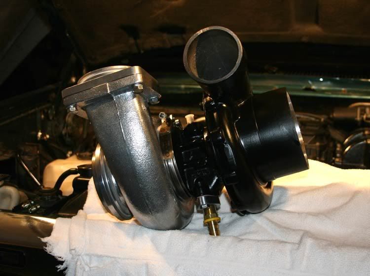
OK so I got a chance to assemble the turbochargers now that everything's coated with something.
Just to PO a few folks, I installed the dreaded Silencer Ring in the secondary as an aerodynamic adjunct. Get over it.
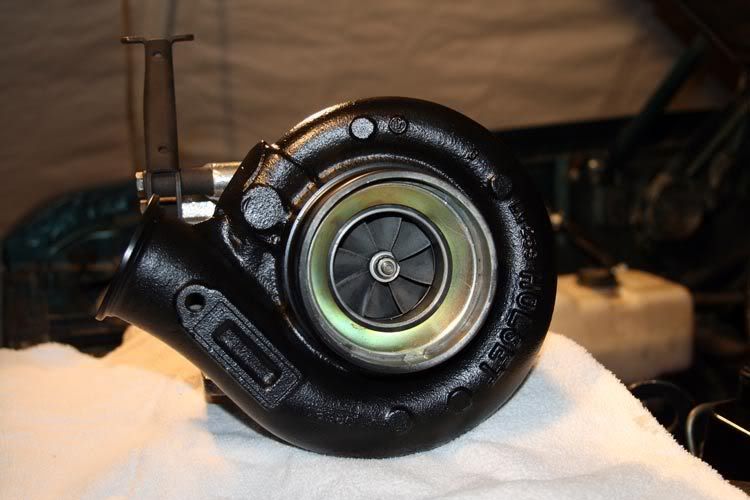
Then nailed on the new secondary oil drain hose adapter.
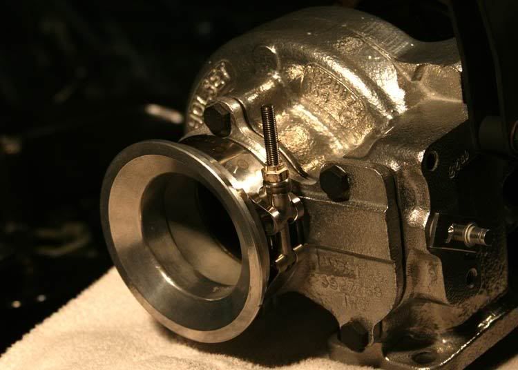
To complete the subassembly of the secondary, I attached the exhaust outlet adapter. This simple little ring allows one to easily upgrade to a turbo running a 4" outlet. It connects with the typical stainless clamp thingy.
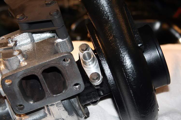
From there I moved on to the primary turbo. There's not really much to do here other than bolt on the hot-pipe to exhaust housing adapter . . . .
Then the oil drain hose adapter.
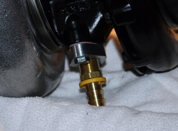
Then I pulled out the OEM turbo oil drain pipe from the block, and installed the new drain hose adapter.
Turn the exhaust manifold upside down, and nail it to the head.

To complete tonight's work, I went ahead and hung the spiny things to get some initial clocking done for the oiling stuff.
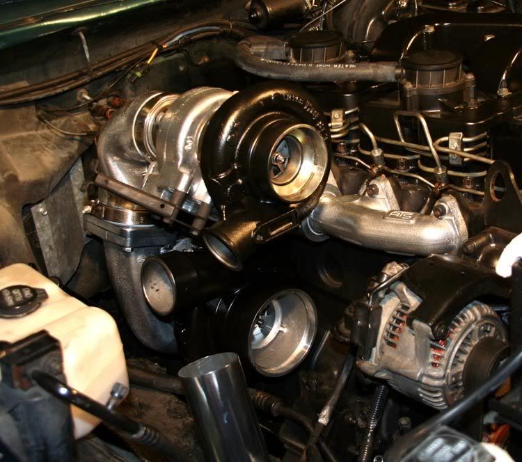
I'll need to cut out some more of the HVAC noise blanket, and then lay over that firewall flange down there to make room for the new down pipe. I may even have to slightly dimple the firewall to help. Not much though. Gonna have to add a new curve to the transmission dip-stick pipe. It looks like I'll be able to simply rotate the AC's suction line at the compressor to clear the primary.
I think it'll work just fine.
Just to PO a few folks, I installed the dreaded Silencer Ring in the secondary as an aerodynamic adjunct. Get over it.
Then nailed on the new secondary oil drain hose adapter.
To complete the subassembly of the secondary, I attached the exhaust outlet adapter. This simple little ring allows one to easily upgrade to a turbo running a 4" outlet. It connects with the typical stainless clamp thingy.
From there I moved on to the primary turbo. There's not really much to do here other than bolt on the hot-pipe to exhaust housing adapter . . . .
Then the oil drain hose adapter.
Then I pulled out the OEM turbo oil drain pipe from the block, and installed the new drain hose adapter.
Turn the exhaust manifold upside down, and nail it to the head.
To complete tonight's work, I went ahead and hung the spiny things to get some initial clocking done for the oiling stuff.
I'll need to cut out some more of the HVAC noise blanket, and then lay over that firewall flange down there to make room for the new down pipe. I may even have to slightly dimple the firewall to help. Not much though. Gonna have to add a new curve to the transmission dip-stick pipe. It looks like I'll be able to simply rotate the AC's suction line at the compressor to clear the primary.
I think it'll work just fine.
09-24-2008, 09:20 AM
#88
1st Generation Admin
Thread Starter
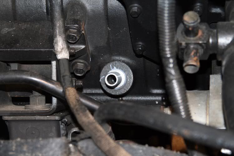
Cuss a little.
More over how tough that thin-wall pipe is! And it's pressed into the block like a hair in a biscuit!
I ended up breaking the pipe from the block and using my torch, I reached just inside the pipe stump and heated a streak annealing it. With that, I was able to easily pull the stump from the block.
More over how tough that thin-wall pipe is! And it's pressed into the block like a hair in a biscuit!
I ended up breaking the pipe from the block and using my torch, I reached just inside the pipe stump and heated a streak annealing it. With that, I was able to easily pull the stump from the block.