
BC's Twin Install / AKA: "I'm Gonna Blow Up My Heap!" (updated as it occurs)
 08-23-2008, 11:54 AM
#46
1st Generation Admin
Thread Starter

Shortly before 01-10-2005 (my first post in these fine forums), the OEM turbocharger's compressor impeller started kissing the inside of the housing. The pieces in question will fit in the turbo oil drain tube. The core's out in the shed. I'll take it apart and see shortly (sorting service calls
 ).
).Thanks guys.

EDIT: DING! DING! DING! We have a winner! Rampage1967 takes the trophy!
Smacking around the OEM turbo has matching pieces fall from it.
Once again, THANKS


 08-23-2008, 06:11 PM
#48
Adminstrator-ess
Ding!
Shortly before 01-10-2005 (my first post in these fine forums), the OEM turbocharger's compressor impeller started kissing the inside of the housing. The pieces in question will fit in the turbo oil drain tube. The core's out in the shed. I'll take it apart and see shortly (sorting service calls ).
Thanks guys.
EDIT: DING! DING! DING! We have a winner! Rampage1967 takes the trophy!
Smacking around the OEM turbo has matching pieces fall from it.
Once again, THANKS
Shortly before 01-10-2005 (my first post in these fine forums), the OEM turbocharger's compressor impeller started kissing the inside of the housing. The pieces in question will fit in the turbo oil drain tube. The core's out in the shed. I'll take it apart and see shortly (sorting service calls
).Thanks guys.
EDIT: DING! DING! DING! We have a winner! Rampage1967 takes the trophy!
Smacking around the OEM turbo has matching pieces fall from it.
Once again, THANKS
That's good news. When you pull that old H1C apart I'm pretty sure you'll find the thrust bushing halfway gone.
 08-24-2008, 04:31 PM
#51
1st Generation Admin
Thread Starter
Sure thing . ... 
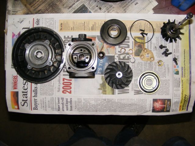
Literally smacking around the old OEM turbo core had this fall from the oil drain port.
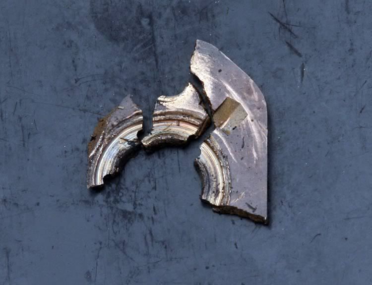
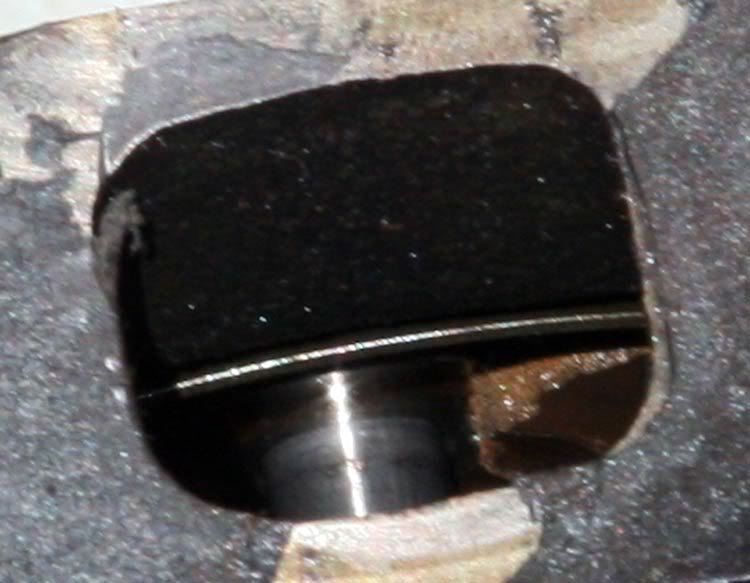
Then peeking inside that port, at where the compressor wheel bearing assembly is suppose to be . . . . That brass looking thing to the right is most likely the balance of the thrust bushing . . .
I do remember an "Event" with the OEM turbo that may very well has been when all this when down.

I'm in the midst of reinstalling the pan. Pics coming soon.
Literally smacking around the old OEM turbo core had this fall from the oil drain port.
Then peeking inside that port, at where the compressor wheel bearing assembly is suppose to be . . . . That brass looking thing to the right is most likely the balance of the thrust bushing . . .
I do remember an "Event" with the OEM turbo that may very well has been when all this when down.
I'm in the midst of reinstalling the pan. Pics coming soon.
08-24-2008, 10:01 PM
#52
1st Generation Admin
Thread Starter
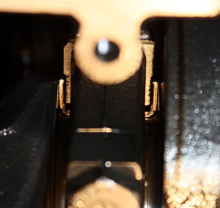
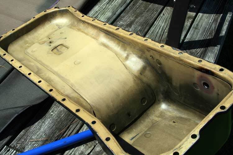
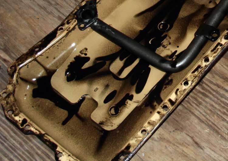
For those wondering about my crankshaft thrust bearing, as best I can see, it appears fine. This image is typical for both sides.
Looking around while in there, we can see the oil pump's intake port as well as the OEM turbocharger oil return port.
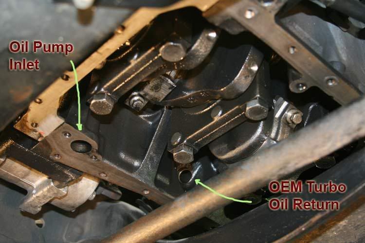
OK, so the whole point of this was to install a new oil drain for the new primary turbocharger. It's my understanding that the OEM oil return port is located too high for the primary turbo to drain properly. Further, I understand one might be asking for problems if trying to Tee into the OEM return with the secondary turbo. Some have no issues.
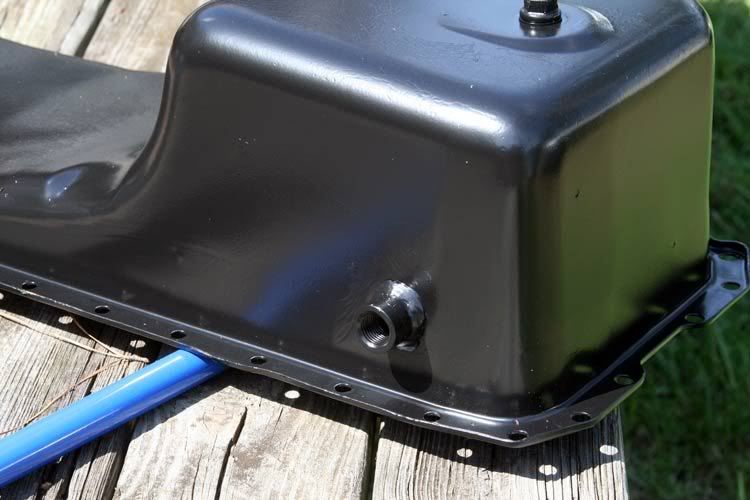
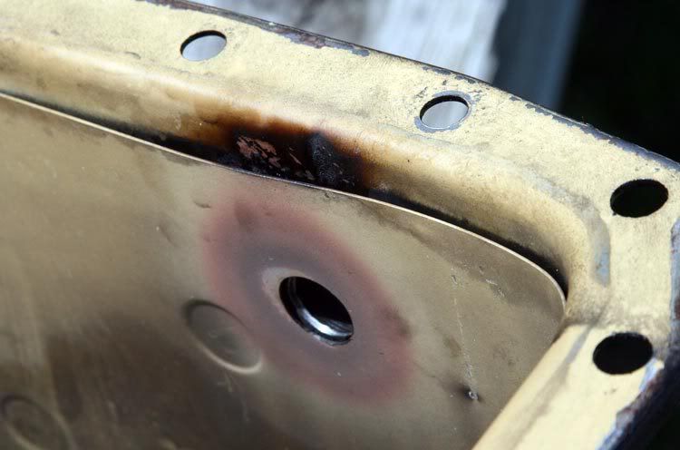
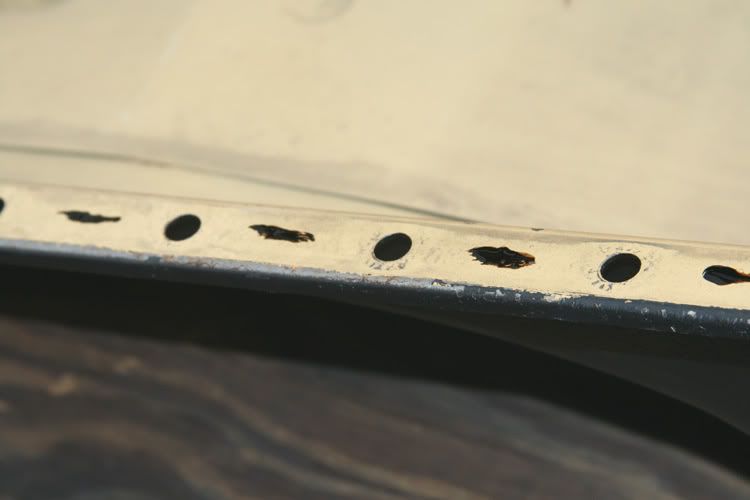
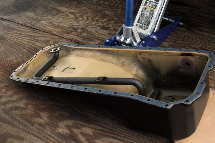
The Cummins 5.9ltr oil pan is of substantial construction for sheet metal. It includes inner panels, perhaps for noise and vibration control.
With the new oil drain located as it is, some toasting of things was apparent when the bung was welded into place. I though it a good idea to blast in between the sheet metal with the pressure washer so as to get out all the crunchies.
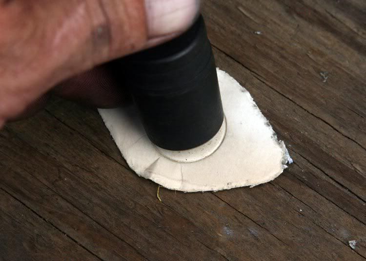
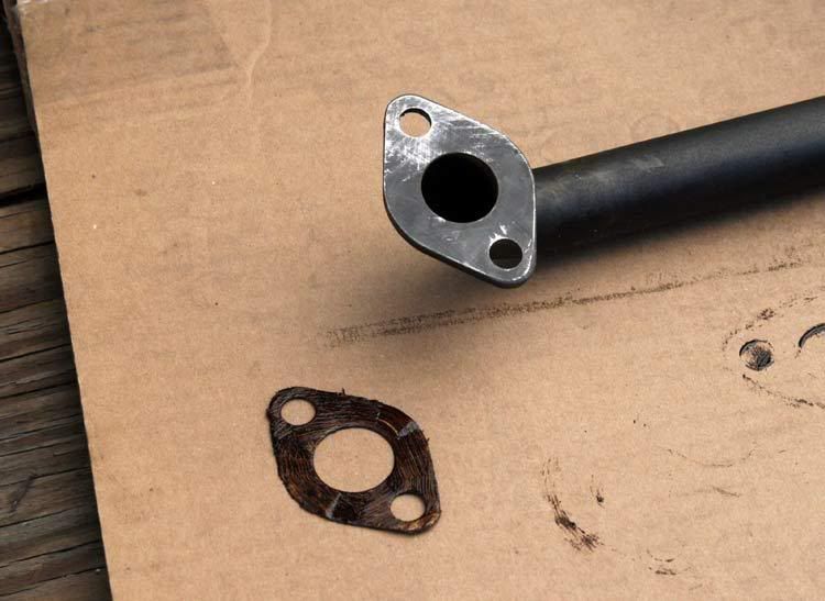
Naturally, when I ordered a replacement oil pan gasket, I completely forgot about the oil pick-up tube's gasket. So I had to make one. Using some heavy single ply cardboard and my small brass headed hammer, I securely mounted the tube and tapped out a new gasket.
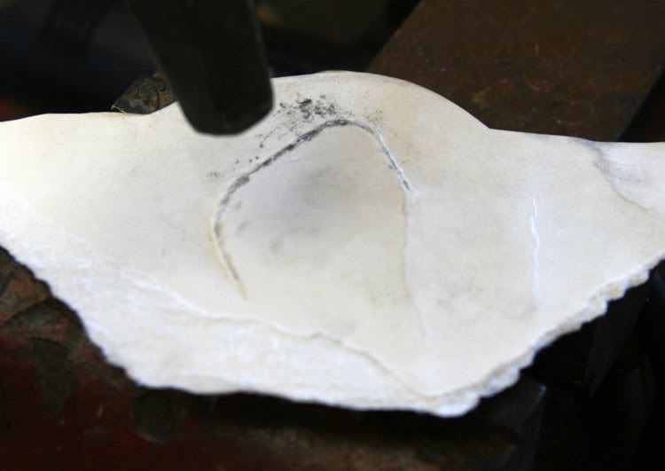
I then used my gasket hole punches to make the appropriate holes . . . .
And then painted both sides with some gasket shellac for additional strength.
Looking around while in there, we can see the oil pump's intake port as well as the OEM turbocharger oil return port.
OK, so the whole point of this was to install a new oil drain for the new primary turbocharger. It's my understanding that the OEM oil return port is located too high for the primary turbo to drain properly. Further, I understand one might be asking for problems if trying to Tee into the OEM return with the secondary turbo. Some have no issues.
The Cummins 5.9ltr oil pan is of substantial construction for sheet metal. It includes inner panels, perhaps for noise and vibration control.
With the new oil drain located as it is, some toasting of things was apparent when the bung was welded into place. I though it a good idea to blast in between the sheet metal with the pressure washer so as to get out all the crunchies.
Naturally, when I ordered a replacement oil pan gasket, I completely forgot about the oil pick-up tube's gasket. So I had to make one. Using some heavy single ply cardboard and my small brass headed hammer, I securely mounted the tube and tapped out a new gasket.
I then used my gasket hole punches to make the appropriate holes . . . .
And then painted both sides with some gasket shellac for additional strength.
08-24-2008, 10:02 PM
#53
1st Generation Admin
Thread Starter
While that shellac dried, I moved on to preparing the oil pan itself. With removing the OEM installed pan, I found no evidence that Cummins used any gasket compound with the original gasket. I decided it best to follow their lead and left well enough alone. Further, the oil pan appears to be coated internally with a Teflon like material as is made evident by the way the oil wants to bead. That would render any adhesives useless.
With that, I did put small smears of shellac on the mounting rails to help hold the new gasket in place while I moved the pan into position.
That being done, I set the pick-up tube, complete with it's new gasket into the pan making it ready to reinstall.
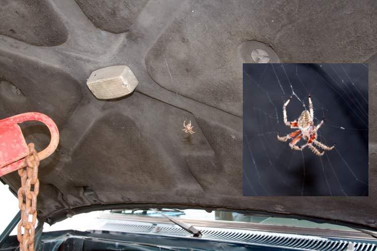
Alrighty then, under the watchful eye of my new friend Margarette . ..
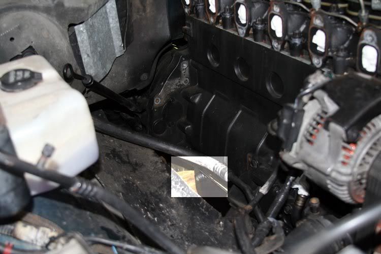
I fired up the John Deere and once again lifted the engine.
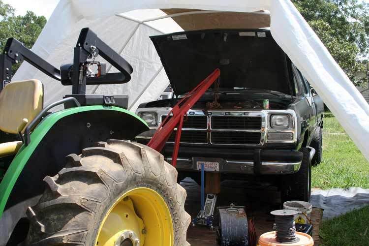
All the way till the rear of the head is leaning on the firewall.
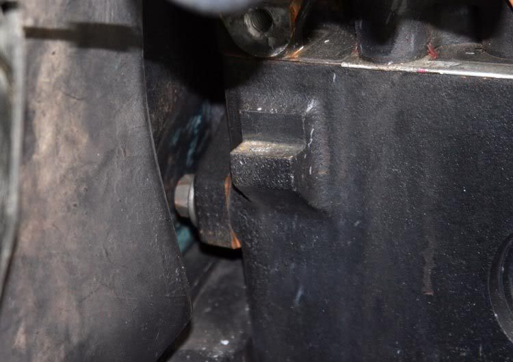
In this image, I've got the pan lifted slightly to hold it in place while I took the photograph. There's room, but just only. I found it necessary to turn the crankshaft over so as to move the number 2 rod journal out of the way. It's tight but easily done.
With that, I did put small smears of shellac on the mounting rails to help hold the new gasket in place while I moved the pan into position.
That being done, I set the pick-up tube, complete with it's new gasket into the pan making it ready to reinstall.
Alrighty then, under the watchful eye of my new friend Margarette . ..
I fired up the John Deere and once again lifted the engine.
All the way till the rear of the head is leaning on the firewall.
In this image, I've got the pan lifted slightly to hold it in place while I took the photograph. There's room, but just only. I found it necessary to turn the crankshaft over so as to move the number 2 rod journal out of the way. It's tight but easily done.
08-24-2008, 10:03 PM
#54
1st Generation Admin
Thread Starter
I found it most helpful to temporarily install one oil pan bolt, back at the driver's rear corner, so as to hold the pan up so I could easily get to the oil pick-up tube flange up front. Be sure to smear a booger (a unit of measure) of RTV type gasket maker right there where the front gear case interfaces with the block (both sides).

With the oil pick-up tube's flange bolted to the block, I then removed that one oil pan bolt so as to allow me to install the remaining two bolts that hold the pick-up tube braces.
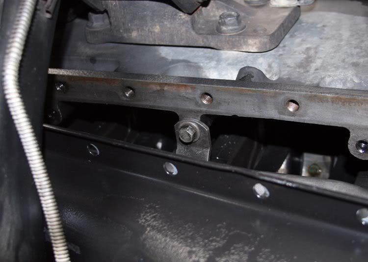
Installing the balance of the pan bolts completes the task.
So there! The second oil drain is in place (excuse the funky image).
Now on to messaging the transmission oil cooler 'n stuff.
With the oil pick-up tube's flange bolted to the block, I then removed that one oil pan bolt so as to allow me to install the remaining two bolts that hold the pick-up tube braces.
Installing the balance of the pan bolts completes the task.
So there! The second oil drain is in place (excuse the funky image).
Now on to messaging the transmission oil cooler 'n stuff.
08-25-2008, 04:54 PM
#56
Adminstrator-ess
08-26-2008, 11:23 PM
#57
alwaysonDTR
Join Date: Dec 2007
Location: Keizer, oregon
Posts: 2,551
Likes: 0
Received 0 Likes
on
0 Posts
Sure thing . ...
Literally smacking around the old OEM turbo core had this fall from the oil drain port.
Then peeking inside that port, at where the compressor wheel bearing assembly is suppose to be . . . . That brass looking thing to the right is most likely the balance of the thrust bushing . . .
I do remember an "Event" with the OEM turbo that may very well has been when all this when down.
I'm in the midst of reinstalling the pan. Pics coming soon.
i think that brass plate should look like this one
larger pic
http://i289.photobucket.com/albums/l...s/DSCF3229.jpg
08-27-2008, 07:49 AM
#58
Registered User
Join Date: May 2004
Location: Golden, Colorado
Posts: 2,867
Likes: 0
Received 0 Likes
on
0 Posts
Well I guess I wasn't right about the bearing, glad I wasn't!! I was thinking that the radius on your pieces weren't large enough but that was the only thing I could think of that would be down there. I also never thought bearings from the turbo could fall down the oil drain. Thats crazy!
Aaron
Aaron
09-01-2008, 12:51 AM
#59
1st Generation Admin
Thread Starter
Aaron, it don't sound right to say it, but I'm glad you were wrong. . . . . . . No. Really. 
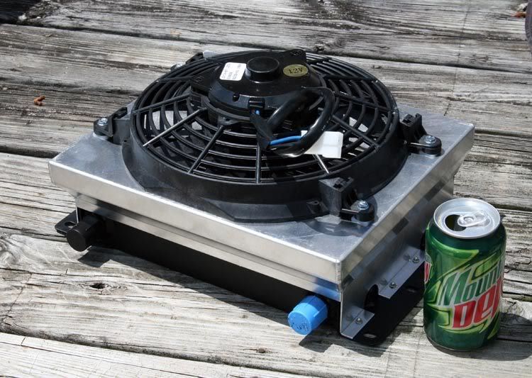
I finally got the chance to deal with mounting that supplemental transmission oil cooler where I wanted it. I took into consideration things such as . . .
- It seems to me that with the fan shroud in the mix, my oil cooler is a bit taller than the OEM cooler. As such, it appears to me that the cooler would sit low on the outside of the frame rail. I think one would be able to see the cooler. I don't want that. The only place I could come up with was just in front of the fuel tank. Inside the frame rails.
- For better protection of the cooler, I thought it'd be a good idea to mount it just above the bottom surface of the frame rail.
- I want it mounted to the truck frame exclusively. Not to the cab or bed.
- Located as such, and considering the cooler/fan is of the Pull-Through design, I figure mounting the thing where it could draw cool air from the ground (so to speak), and have it exhaust the hot air out the top (against the bottom of the cab).
- This location places the cooler assembly within 4" ~ 6" of the drive-shaft / universal joint right there where it comes out of the transfer case. So I've got to maintain enough space there so as to easily accommodate a safety shield when/if it comes to it. As such, I'll have to mount the cooler high enough so the plumbing will nest inside and above the lower flange of the frame rail. Since that universal joint, freshly greased, slings grease everywhere, I should make some kind of a shield to keep the grease from getting into the fins of the cooler, making a mess. I ought to make it somewhat beefy so as to offer some minimum of protection to the cooler should the drive-shaft get out of line.
- This location will place the cooler behind and above the transfer case's skid-plate assembly.
- Etc . . . . etc . . .
Y'all keeping up with this?
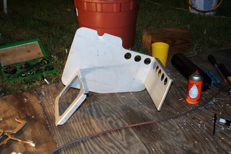
Anyhoo, this is what I came up with . . . . .
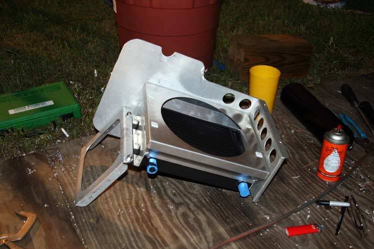
This is that same bracket assembly with the supplemental cooler (less fan) attached.
Here's a shot of it as seen from outside the truck, looking underneath. (That's the forward end of the fuel tank in the top/right of the image).
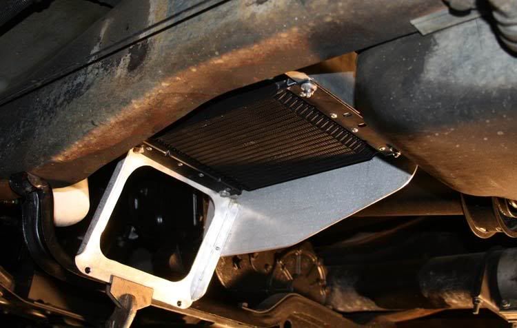
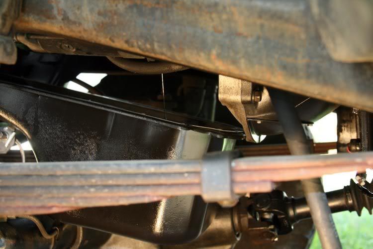
And here's from under the truck, looking out and forward.
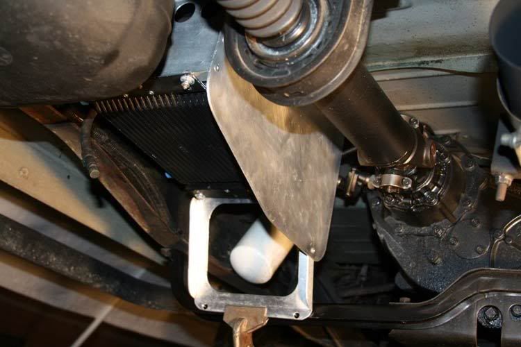
As you see it in the above images, the rear of the assembly is attached to that frame cross-member there above the forward end of the fuel tank. The front of the assembly is attached to the rear transfer skid-plate cross-member.
I used some highway sign aluminum stock I got from the local scrap-yard. About 16 gauge for the smaller rear bracket, and 8 gauge(ish) for the front bracket and that side shield. Aluminum rivets hold the assembly together. Machine bolts, flat washers (both sides) and aviation type lock-nuts hold the cooler to the bracket assembly as well as the whole thing to the frame of the truck.
Mounted as such, I think there's just enough room above/around the top of the assembly to be able to flow a decent amount of hot exhaust air.
The paint's drying. I'll mount it tomorrow. From there I'm gonna undo that existing supplemental transmission oil filter (white in above image) so I can remount it with the OEM transmission fluid heat exchanger (had to move it to make room for the new primary turbo).
It's slow but, . . . .. so far so good.
I finally got the chance to deal with mounting that supplemental transmission oil cooler where I wanted it. I took into consideration things such as . . .
- It seems to me that with the fan shroud in the mix, my oil cooler is a bit taller than the OEM cooler. As such, it appears to me that the cooler would sit low on the outside of the frame rail. I think one would be able to see the cooler. I don't want that. The only place I could come up with was just in front of the fuel tank. Inside the frame rails.
- For better protection of the cooler, I thought it'd be a good idea to mount it just above the bottom surface of the frame rail.
- I want it mounted to the truck frame exclusively. Not to the cab or bed.
- Located as such, and considering the cooler/fan is of the Pull-Through design, I figure mounting the thing where it could draw cool air from the ground (so to speak), and have it exhaust the hot air out the top (against the bottom of the cab).
- This location places the cooler assembly within 4" ~ 6" of the drive-shaft / universal joint right there where it comes out of the transfer case. So I've got to maintain enough space there so as to easily accommodate a safety shield when/if it comes to it. As such, I'll have to mount the cooler high enough so the plumbing will nest inside and above the lower flange of the frame rail. Since that universal joint, freshly greased, slings grease everywhere, I should make some kind of a shield to keep the grease from getting into the fins of the cooler, making a mess. I ought to make it somewhat beefy so as to offer some minimum of protection to the cooler should the drive-shaft get out of line.
- This location will place the cooler behind and above the transfer case's skid-plate assembly.
- Etc . . . . etc . . .
Y'all keeping up with this?
Anyhoo, this is what I came up with . . . . .
This is that same bracket assembly with the supplemental cooler (less fan) attached.
Here's a shot of it as seen from outside the truck, looking underneath. (That's the forward end of the fuel tank in the top/right of the image).
And here's from under the truck, looking out and forward.
As you see it in the above images, the rear of the assembly is attached to that frame cross-member there above the forward end of the fuel tank. The front of the assembly is attached to the rear transfer skid-plate cross-member.
I used some highway sign aluminum stock I got from the local scrap-yard. About 16 gauge for the smaller rear bracket, and 8 gauge(ish) for the front bracket and that side shield. Aluminum rivets hold the assembly together. Machine bolts, flat washers (both sides) and aviation type lock-nuts hold the cooler to the bracket assembly as well as the whole thing to the frame of the truck.
Mounted as such, I think there's just enough room above/around the top of the assembly to be able to flow a decent amount of hot exhaust air.
The paint's drying. I'll mount it tomorrow. From there I'm gonna undo that existing supplemental transmission oil filter (white in above image) so I can remount it with the OEM transmission fluid heat exchanger (had to move it to make room for the new primary turbo).
It's slow but, . . . .. so far so good.