
Beefing-Up My A518 Transmission (Updated As It Occurs)
 07-11-2010, 09:19 PM
#16
1st Generation Admin
Thread Starter
That completes the rebuild/repair of the rear clutch-pack. Dunk it in some clean ATF and stick it in a clean plastic trash bag for later .. ..

Now that I've got all the new parts sorted, I can build the intermediate shaft assembly.
NOTE: My stock/OEM A518 (46RH) came with, both front and rear, 4-pinion planetary gear-sets with aluminum carriers. Here, I'm upgrading to 6-pinion gear-sets with steel carriers. The front gear-set is apparently exclusive to the newer 48RE series transmissions. I'm not sure when the rear 6-pinion came along.
Anyhoot, while it's for the most part, a drop-in affair, there are a few things that need updating to support the new gear-sets.
OK, I broke my original intermediate shaft, so I got a new one. I had to get a newer, '94 and up shaft as the splines that engage the front planet carrier changed. Further, there were some changes in the thrust bearings related to the newer gear-sets. Basically, they got wider to better support the loads presented.
My stock/OEM A518 came with a steel race for the thrust bearing at the back of the rear planet gear-set (between the annulus gear and the carrier). The newer 6-pinion unit uses a annulus gear that's been machined for the thrust washer.
You can see the machining inside that annulus gear mounted on the new shaft . . .
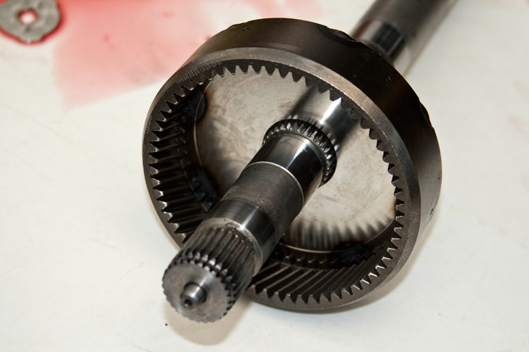
Here's the new 6-pinion rear planetary with the steel carrier. You can see the new, wider thrust bearing that rides against that machined surface mentioned above.

Sliding that boy on the shaft shows us the other thrust bearing.

That other thrust bearing rides against a steel race on the outside of the drive-shell (see green arrow). Apparently, used, 48RE steel races that are wider to fit the newer, wider thrust bearings are hard to come by. I'm being told it'll be just fine running the narrower race with the wider bearing (there's about an eighth of an inch overhang).
I've also installed a new Sun gear in the shell that renews those internal bushings as well as the teeth.

Mounting that on the intermediate shaft lets me go to the other side of the drive-shell to install the front planetary gear-set. Here again, I've a similar situation with the old and new thrust washers. Somewhere in the evolution of our transmissions, the thickness of the shell where it engages the sun-gear was increased. As with the newer rear planets, the newer front planets also went to the wider thrust washers.
Because my drive-shell was in good shape and a newer one adds to the bill, I stuck with my original (I'm told this area is not one for failure). The green arrow points to the original design thrust bearing.

On the left of the image below is the new 6-pinion w/steel carrier planetary. That green arrow on the left points to a thin plastic bushing that apparently is required with the newer gear-set (the A518 doesn't use it).
On the right of the image is my original annulus gear for the front planet stuff. The green arrow points to the older/narrower thrust bearing's footprint. The newer thrust bearing shown installed on the carrier is much wider to better support the loads.

I seem to have forgotten to get a pic of the installed front planetary gear-set, but doing so and installing the original snap ring gives me an assembly end-play of 0.042". That's right there at the loose side of the factory spec of 0.048" max. Considering some breaking-in slop to come about, I need to get a thicker snap-ring to tighten it up some.
Dunk it in clean fluid and into a trash bag for later.
Now that I've got all the new parts sorted, I can build the intermediate shaft assembly.
NOTE: My stock/OEM A518 (46RH) came with, both front and rear, 4-pinion planetary gear-sets with aluminum carriers. Here, I'm upgrading to 6-pinion gear-sets with steel carriers. The front gear-set is apparently exclusive to the newer 48RE series transmissions. I'm not sure when the rear 6-pinion came along.
Anyhoot, while it's for the most part, a drop-in affair, there are a few things that need updating to support the new gear-sets.
OK, I broke my original intermediate shaft, so I got a new one. I had to get a newer, '94 and up shaft as the splines that engage the front planet carrier changed. Further, there were some changes in the thrust bearings related to the newer gear-sets. Basically, they got wider to better support the loads presented.
My stock/OEM A518 came with a steel race for the thrust bearing at the back of the rear planet gear-set (between the annulus gear and the carrier). The newer 6-pinion unit uses a annulus gear that's been machined for the thrust washer.
You can see the machining inside that annulus gear mounted on the new shaft . . .
Here's the new 6-pinion rear planetary with the steel carrier. You can see the new, wider thrust bearing that rides against that machined surface mentioned above.
Sliding that boy on the shaft shows us the other thrust bearing.
That other thrust bearing rides against a steel race on the outside of the drive-shell (see green arrow). Apparently, used, 48RE steel races that are wider to fit the newer, wider thrust bearings are hard to come by. I'm being told it'll be just fine running the narrower race with the wider bearing (there's about an eighth of an inch overhang).
I've also installed a new Sun gear in the shell that renews those internal bushings as well as the teeth.
Mounting that on the intermediate shaft lets me go to the other side of the drive-shell to install the front planetary gear-set. Here again, I've a similar situation with the old and new thrust washers. Somewhere in the evolution of our transmissions, the thickness of the shell where it engages the sun-gear was increased. As with the newer rear planets, the newer front planets also went to the wider thrust washers.
Because my drive-shell was in good shape and a newer one adds to the bill, I stuck with my original (I'm told this area is not one for failure). The green arrow points to the original design thrust bearing.
On the left of the image below is the new 6-pinion w/steel carrier planetary. That green arrow on the left points to a thin plastic bushing that apparently is required with the newer gear-set (the A518 doesn't use it).
On the right of the image is my original annulus gear for the front planet stuff. The green arrow points to the older/narrower thrust bearing's footprint. The newer thrust bearing shown installed on the carrier is much wider to better support the loads.
I seem to have forgotten to get a pic of the installed front planetary gear-set, but doing so and installing the original snap ring gives me an assembly end-play of 0.042". That's right there at the loose side of the factory spec of 0.048" max. Considering some breaking-in slop to come about, I need to get a thicker snap-ring to tighten it up some.
Dunk it in clean fluid and into a trash bag for later.
 07-11-2010, 09:20 PM
#17
1st Generation Admin
Thread Starter
Moving on to the front (intermediate) clutch-pack has me concerned about that big bushing. Looks worn to me. I'm gonna replace it.

Looking hard at the trans fluid 10-lobe pump rotor has me think it's OK. Looking next to the inner lobes, one can see some light scuffing as though it's been spinning back and forth a little . . . . . I think.
What'chawl reckon?

Looking hard at the trans fluid 10-lobe pump rotor has me think it's OK. Looking next to the inner lobes, one can see some light scuffing as though it's been spinning back and forth a little . . . . . I think.
What'chawl reckon?
07-12-2010, 03:29 PM
#20
1st Generation Admin
Thread Starter
Anybody got any tips on adjusting the intermediate shaft assembly's end-play? It appears that final snap-ring is in fact NOT a selectable kind with different sizes available. My mess is toward the loose maximum of 0.048" (currently my mess is at 0.042"). I'm thinking I should snug things up a few thousandths.
 07-12-2010, 04:48 PM
#21
Guest
Posts: n/a
Yes, the lugs on the inside of the inner rotor engage the slots on the torque converter hub. Whoever told you that front snap ring on the intermediate shaft only comes in one thickness doesn't know what they are talking about, they are indeed selectable, should be 3 or 4 thicknesses. I would be a lot more comfortable with the endplay down around .025" or thereabouts. The reason for the torlon bushing that goes between the front carrier and the front annulus is the original design for 727 was an aluminum carrier which didn't need a bushing, the aluminum hub was the bearing.
07-12-2010, 06:34 PM
#22
1st Generation Admin
Thread Starter
Yes, the lugs on the inside of the inner rotor engage the slots on the torque converter hub. Thanks. Can I get a 2nd on getting the big-lug rotor?
Whoever told you that front snap ring on the intermediate shaft only comes in one thickness doesn't know what they are talking about, they are indeed selectable, should be 3 or 4 thicknesses. I would be a lot more comfortable with the endplay down around .025" or thereabouts. That's what I thought. I should be a little clearer in that the one parts house I snuck by while working today (TranStar) didn't list anything other than a used one. He didn't have anything about different sizes. I'll check a few alternate sources.
The reason for the torlon bushing that goes between the front carrier and the front annulus is the original design for 727 was an aluminum carrier which didn't need a bushing, the aluminum hub was the bearing. That makes sense. Thanks

-> ALL input, suggestions, rude comments, etc are welcomed.
I'm putting together the front clutch-pack. Just finished replacing that bushing . .. .. . . . .
07-12-2010, 09:34 PM
#23
1st Generation Admin
Thread Starter
Digging around on the internet, I can't find one source of the selectable snap-rings that secure the front planetary to the intermediate shaft. If anybody lists one, it's just that: One (no size referenced). I've not tried a Dodge dealer. Maybe I'm not using the right search term . . . . ?
I am however, seeing many references to a Sonnax shim kit specifically for tightening the end-play of the intermediate assembly. It amounts to a bag of ten: 0.010" shims that are apparently installed between the thrust washer and the rear planet. The problem with it is it's only for the 3 & 4-tab thrust washers. Not the wider, 6-tab 48RE stuff. (I got a pair of tin-snips that beg to differ).
Thinking out loud . . . .. I could go back and use a 46RH thrust washer (3-tab) there instead of the 48RE thrust washer (6-tab). I've still got the 46RH race in there (PATC has the 48RE race for $4). As currently installed, the 48 washer isn't offering any real advantage with the 46 race.
- I guess I can go back to the 46 thrust washer/race (3-tab) set-up, and then shim it with the Sonnax stuff. That would work.
I did manage to get the front clutch rebuilt including replacing that worn internal bushing . . . .

But then found I had the wrong replacement bushing for inside the pump-housing thing . ..
I am however, seeing many references to a Sonnax shim kit specifically for tightening the end-play of the intermediate assembly. It amounts to a bag of ten: 0.010" shims that are apparently installed between the thrust washer and the rear planet. The problem with it is it's only for the 3 & 4-tab thrust washers. Not the wider, 6-tab 48RE stuff. (I got a pair of tin-snips that beg to differ).
Thinking out loud . . . .. I could go back and use a 46RH thrust washer (3-tab) there instead of the 48RE thrust washer (6-tab). I've still got the 46RH race in there (PATC has the 48RE race for $4). As currently installed, the 48 washer isn't offering any real advantage with the 46 race.
- I guess I can go back to the 46 thrust washer/race (3-tab) set-up, and then shim it with the Sonnax stuff. That would work.
I did manage to get the front clutch rebuilt including replacing that worn internal bushing . . . .
But then found I had the wrong replacement bushing for inside the pump-housing thing . ..
 07-13-2010, 10:09 AM
#26
1st Generation Admin
Thread Starter
As shown above, I've got it set-up with approximately 0.070" clearance.
07-14-2010, 09:40 PM
#27
1st Generation Admin
Thread Starter
Digging around on the internet, I can't find one source of the selectable snap-rings that secure the front planetary to the intermediate shaft. If anybody lists one, it's just that: One (no size referenced). I've not tried a Dodge dealer. Maybe I'm not using the right search term . . . . ?
I am however, seeing many references to a Sonnax shim kit specifically for tightening the end-play of the intermediate assembly. It amounts to a bag of ten: 0.010" shims that are apparently installed between the thrust washer and the rear planet. The problem with it is it's only for the 3 & 4-tab thrust washers. Not the wider, 6-tab 48RE stuff. (I got a pair of tin-snips that beg to differ).
Thinking out loud . . . .. I could go back and use a 46RH thrust washer (3-tab) there instead of the 48RE thrust washer (6-tab). I've still got the 46RH race in there (PATC has the 48RE race for $4). As currently installed, the 48 washer isn't offering any real advantage with the 46 race.
- I guess I can go back to the 46 thrust washer/race (3-tab) set-up, and then shim it with the Sonnax stuff. That would work.
Well, it turns out I can't put the shim(s) behind the front thrust washer of the rear planet. The 2003+ 48RE 6-pinion rear planetary must use the wider thrust washer (48RE). The wider 48RE thrust washer includes a wider pattern for the 6 tabs. That wide tab pattern in the planet won't accommodate the narrower, smaller diameter 3-tab thrust washer (46RH). So I left it like it was.
> There is however that 46RH 3-tab thrust washer that's in between the front planet and the drive-shell (I'm still using the stock/OEM 46RH drive-shell).
I snuck two of the 0.010" shims under that thrust washer and put it all back together using my original snap ring . . . . 
With that, I'm right at 0.019" end-play.
 The FSM wants between 0.006" ~ 0.048". A 0.006 ~ 0.010" minimum end-play is preferred.
What's next? The valve-body, or the main case . . . . .. BC flips a coin . . . . . .

 07-18-2010, 11:25 AM
#30
Registered User
Join Date: Apr 2007
Location: Southern New Jersey
Posts: 4,062
Likes: 0
Received 0 Likes
on
0 Posts